Ringless-collector conductor roll

a conductor roll and ringless technology, applied in the direction of electrolysis processes, electrolysis components, cells, etc., can solve the problems of frequent repair of cu plating on the roll shaft, and the cost of the conductor roll, and achieve the effect of increasing the bonding strength between the shaft material steel and the cu plating

Inactive Publication Date: 2001-03-06
NIPPON STEEL CORP
View PDF5 Cites 3 Cited by
  • Summary
  • Abstract
  • Description
  • Claims
  • Application Information

AI Technical Summary

Benefits of technology

An object of the present invention is to provide a ringless-collector conductor roll which obviates the burning trouble, which makes removal and installation of the C rings and adjustment of the sliding contact unnecessary, and which extends the life of the sliding collector parts.
When the electroplated Cu layer is provided on the outer peripheral surface of the shaft ends of a conductor roll, the Cu plating layer is firmly bonded to the outer peripheral surface of the roll shaft, and the contact resistance between the plating layer and the shaft during the application of a current is significantly lowered compared with that between the C rings and the roll shaft at the time when the C rings are mounted on the roll shaft.
As a result of a significant decrease in the contact resistance, heat generation caused by the application of a current is greatly decreased, and the temperature is also lowered. A difference between the thermal expansion of the roll shaft and that of the electroplated Cu layer thus becomes small, and peeling at the interface is prevented. Consequently, poor contact between the outer peripheral surface of the roll shaft and the electroplated Cu layer is effectively prevented during the application of a current.
Furthermore, when the electroplated Cu layer is provided on the outer peripheral surface of the CDR shaft ends, the surface hardness (Vickers hardness) increases by about at least 200%, and the frictional resistance decreases to about up to a half compared with cast Cu (Vickers hardness: 35 to 50 Hv). Although reasons for the improvement of the surface hardness (Vickers hardness) by about at least 200% and the decrease of the frictional resistance to up to a half are not definite, the reasons may be inferred to be as described below. The difference is probably based on the fact that in the electroplated Cu layer, the crystalline structure of Cu constituting the Cu layer is formed by electron bonding and is dense compared to cast Cu in which the crystalline structure of Cu constituting cast Cu is coarse. Since the electroplated Cu layer has a high surface hardness and a low frictional resistance compared with the cast Cu-made C rings, the amount of wear caused by sliding diminishes when brushes are contacted with the C rings.
Furthermore, since the outer diameter of the roll shaft on which the electroplated Cu layer is provided is small compared with that of the C rings, the sliding distance per rotation of the CDR becomes small when the brushes are contacted with the Cu layer. The wear amount of the brushes can be diminished due to the decreased sliding distance in combination with the lowered frictional resistance mentioned above.
In addition, the bonding strength between the shaft material steel and the Cu plating may be increased by forming a Ni plating layer which has a thickness of about 3 to 7 .mu.m on the outer peripheral surface of the steel-made roll shaft ends and then forming a Cu plating layer as described above on the Ni plating layer.

Problems solved by technology

When the thickness of the electroplated Cu layer is too small, repairing of the Cu plating on the roll shaft becomes frequent.
When the thickness of the electroplated Cu layer is too large, the conductor roll tends to become costly.

Method used


Image

  • Ringless-collector conductor roll
  • Ringless-collector conductor roll

Examples


Embodiment Construction

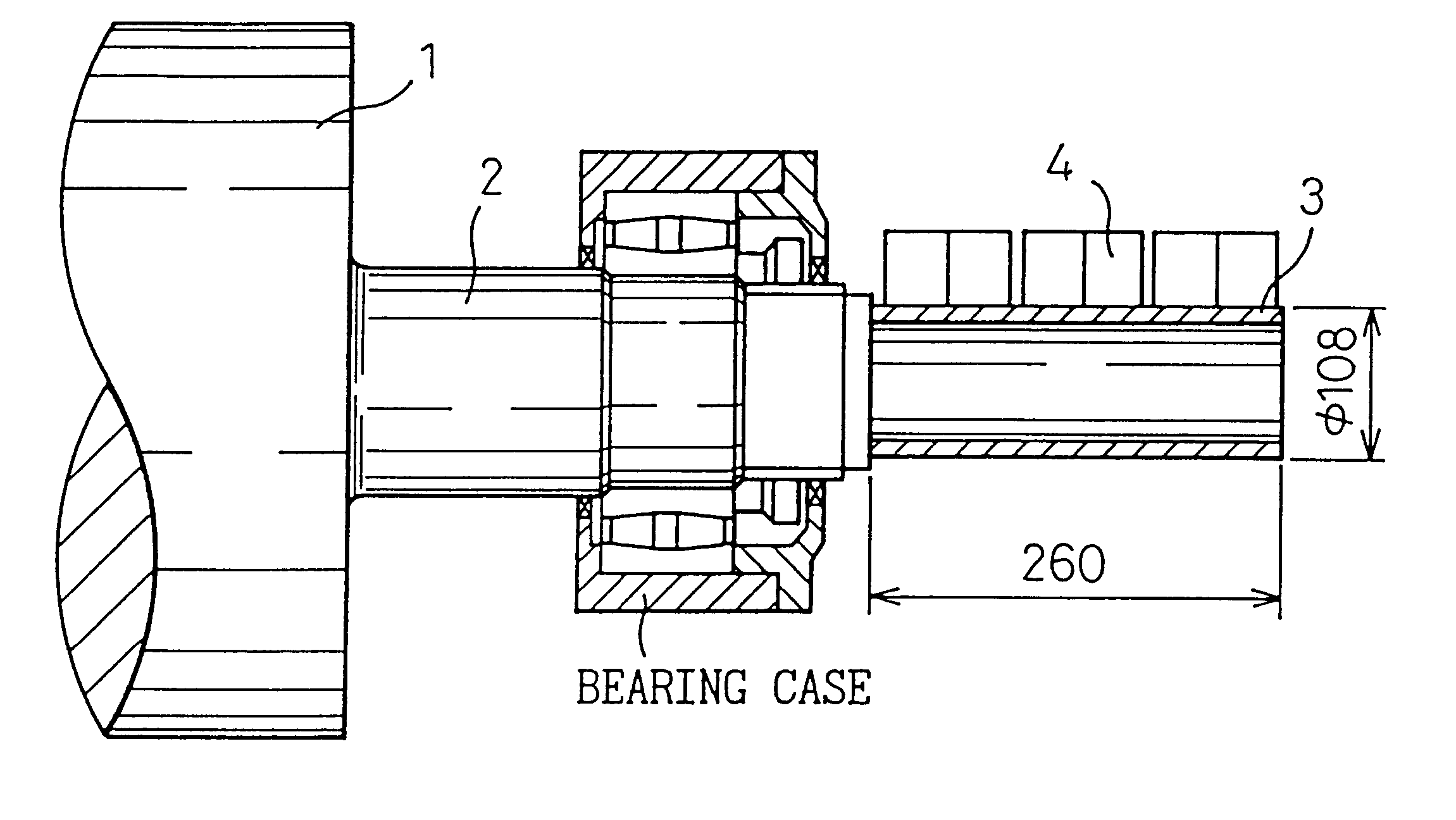
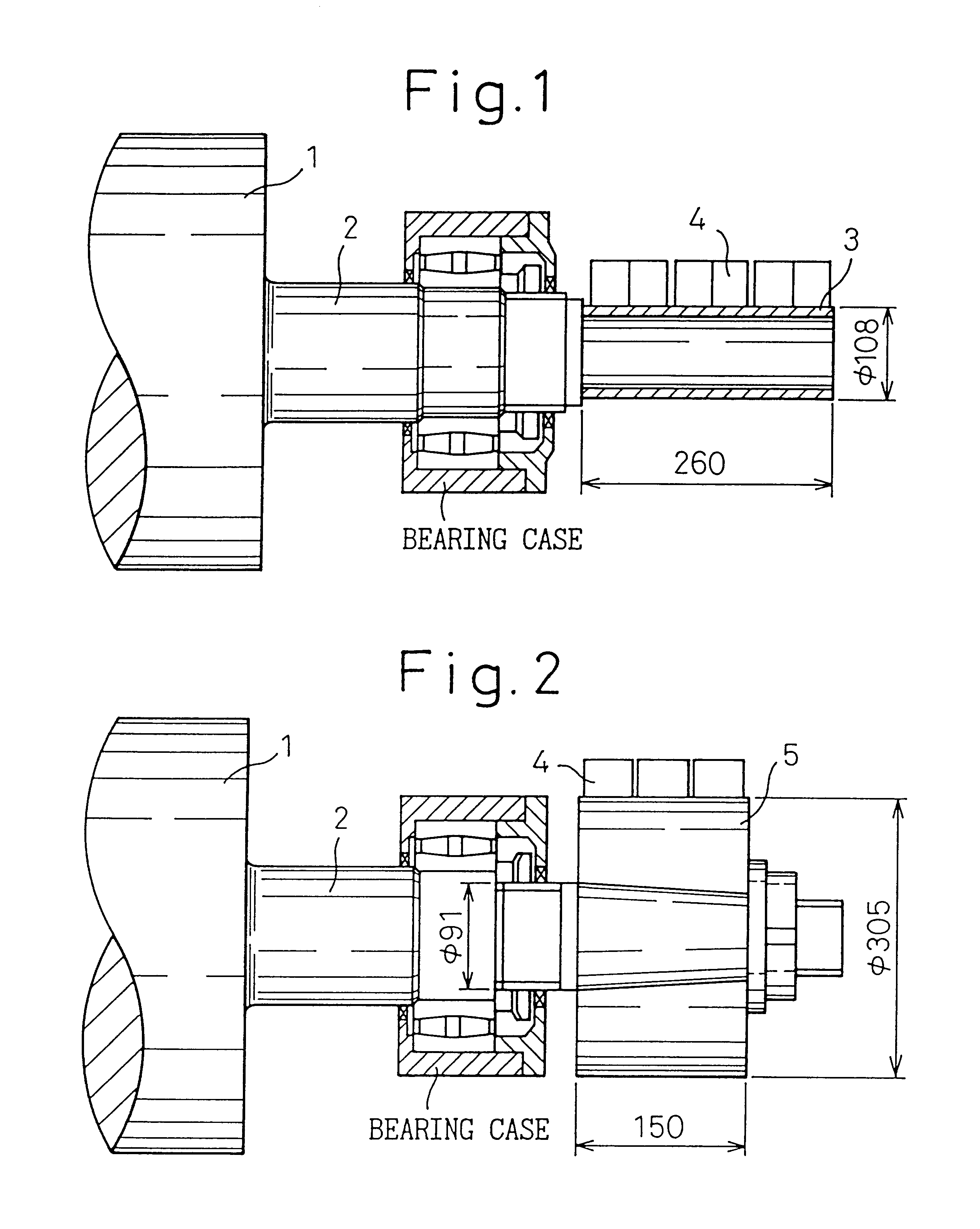
Next, the ringless-collector conductor roll of the present invention will be explained in detail with reference to examples.

A conductor roll 1 having a shaft form shown in FIG. 1 was prepared. For the purpose of increasing the bonding strength between the shaft material steel and the Cu plating, a roll shaft portion 2 in FIG. 1 which was masked except for the outer peripheral surface was immersed in an electrolytic solution containing from 250 to 300 g / l of Ni sulfate, from 40 to 60 g / l of Ni chloride, and from 40 to 50 g / l of boric acid, and having a solution temperature of 55.+-.1.degree. C. and a pH of 3.8 to 4.8. Electroplating was then conducted at a current density of 4 A / dm.sup.2 to form a Ni plating layer having a thickness of 5 .mu.m on the outer peripheral surface. After washing with water, the roll shaft portion in FIG. 1 which was masked except for the outer peripheral surface was immersed in an electrolytic solution containing 200 g / l of Cu sulfate, 30 g / l of sulfuric a...


PUM

PropertyMeasurementUnit
thicknessaaaaaaaaaa
thicknessaaaaaaaaaa
thicknessaaaaaaaaaa

Abstract

An object of the present invention is to provide a conductor roll which obviates burning troubles caused by poor contact between the collector rings (C rings) and the roll shafts, which makes removal and installation of the C rings and operation of sliding contact adjustment unnecessary during the repairing operation of the roll body, and which extends the life of the sliding collector parts. The ringless-collector conductor roll according to the present invention comprises an electroplated Cu layer provided on the outer peripheral surface of the shaft ends of the conductor roll and having a Vickers hardness of at least 100 Hv, the electroplated Cu layer being directly contacted with brushes.

Description

The present invention relates to a conductor roll used in an electroplating apparatus.Electroplating has heretofore been conducted by mounting collector rings (referred to as C rings hereinafter) on both shaft ends of a conductor roll (referred to as a CDR hereinafter), and applying a current through brushes. For the purpose of maintaining the plating stability and the stabilized operation, it is important to ensure the current-conducting properties in the collector portions while it is naturally important to maintain the surface properties of the CDR body directly contacted with a steel strip.Conventional CDRs each have cast Cu-made C rings which are larger than the diameter of the steel-made roll shaft and which are mounted on the right and left roll shaft ends, and an electric current is applied to the C rings. The conventional CDRs, therefore, have the following problems (1) to (3).(1) Poor contact between the C rings and the roll shaft often produces burning troubles of brushes...

Claims


Application Information

Patent Timeline
Patent Type & Authority Patents(United States)
IPC IPC(8): C25D7/06
CPCC25D7/0657C25D7/06
Inventor YOKOGAWA, HIROYUKI
Owner NIPPON STEEL CORP
Why Eureka
Try Eureka