Apparatus for monitoring consumable parts

a technology for consumable parts and apparatuses, applied in the direction of combustion air/fuel air treatment, instruments, separation processes, etc., can solve the problems of downstream internal combustion engine unprotected, unsuitable or wrong filter elements installed, and maintenance switches that do not check the filter element themselves, so as to prevent the start-up of the internal combustion engine, save additional cabling, and prevent damage to the engine

Inactive Publication Date: 2006-08-31
MANN HUMMEL GMBH
View PDF5 Cites 12 Cited by
  • Summary
  • Abstract
  • Description
  • Claims
  • Application Information

AI Technical Summary

Benefits of technology

[0010] The chip reader is configured in such a way that it can detect and retrieve the data from the chip installed in the consumable part. Thus, the chip reader can determine whether the specified consumable part has been installed. If a “wrong” component is installed, a corresponding message may be output, so that the proper component can be installed. The message that a “wrong” component has been installed may be output on a display. In addition, however, the startup of the internal combustion engine may also be prevented in order the prevent damage to the engine. Because the chip reader requires power to detect the data stored on the chip, it is connected to the voltage supply of the maintenance switch. This eliminates the need for an additional voltage supply for the chip reader, thereby saving additional cabling. This has a positive effect on the component costs, the required installation space and the installation of the device. It is furthermore advantageous if the chip reader is integrated into the housing of the maintenance switch. As a result, only a single component needs to be installed, and the chip reader is mounted at the correct location without any added complexity.
[0011] In accordance with one advantageous embodiment of the invention, the reader has an antenna, which is likewise integrated into the maintenance switch. The antenna is thus protected against damage and does not need to be mounted separately. The antenna is disposed at a location within the maintenance switch that is advantageous for detecting the chip data. Ideally, this location is the area lying closest to the chip, so that the antenna requires a minimum amount of power and cannot interfere with components in the vicinity.
[0012] In accordance with another advantageous embodiment of the invention, the reader is connected to the display via the data link of the maintenance indicator. It is technically readily feasible to separate the data of the maintenance switch from the data of the chip reader, so that a corresponding output to the display can be effected. The data may be output on a common display or on two separate displays, such that the one display indicates the operability of the consumable part and the other display indicates the use of a specified consumable part. Thus, the functioning of the consumable part can be monitored independently of the use of a consumable part conforming to specifications.
[0013] In a specific preferred embodiment of the invention, the consumable part or part which wears out and needs replacement is a filter element for filtering a fluid in an internal combustion engine. The fluid to be filtered may, for example, be the intake air or the lubricating oil of an internal combustion engine. By integrating the chip reader into the maintenance switch, the monitoring of such filter elements can be realized cost-effectively and with little complexity because these filter elements already have a maintenance switch with the corresponding voltage supply and data lines, so that monitoring of the installed filter element requires no additional installation space.

Problems solved by technology

The known maintenance switches, however, have the drawback that they do not check the filter element itself.
Therefore, unsuitable or wrong filter elements can be installed, which may leave a downstream internal combustion engine unprotected and under some circumstances may damage the engine.

Method used


Image

  • Apparatus for monitoring consumable parts
  • Apparatus for monitoring consumable parts
  • Apparatus for monitoring consumable parts

Examples


Embodiment Construction

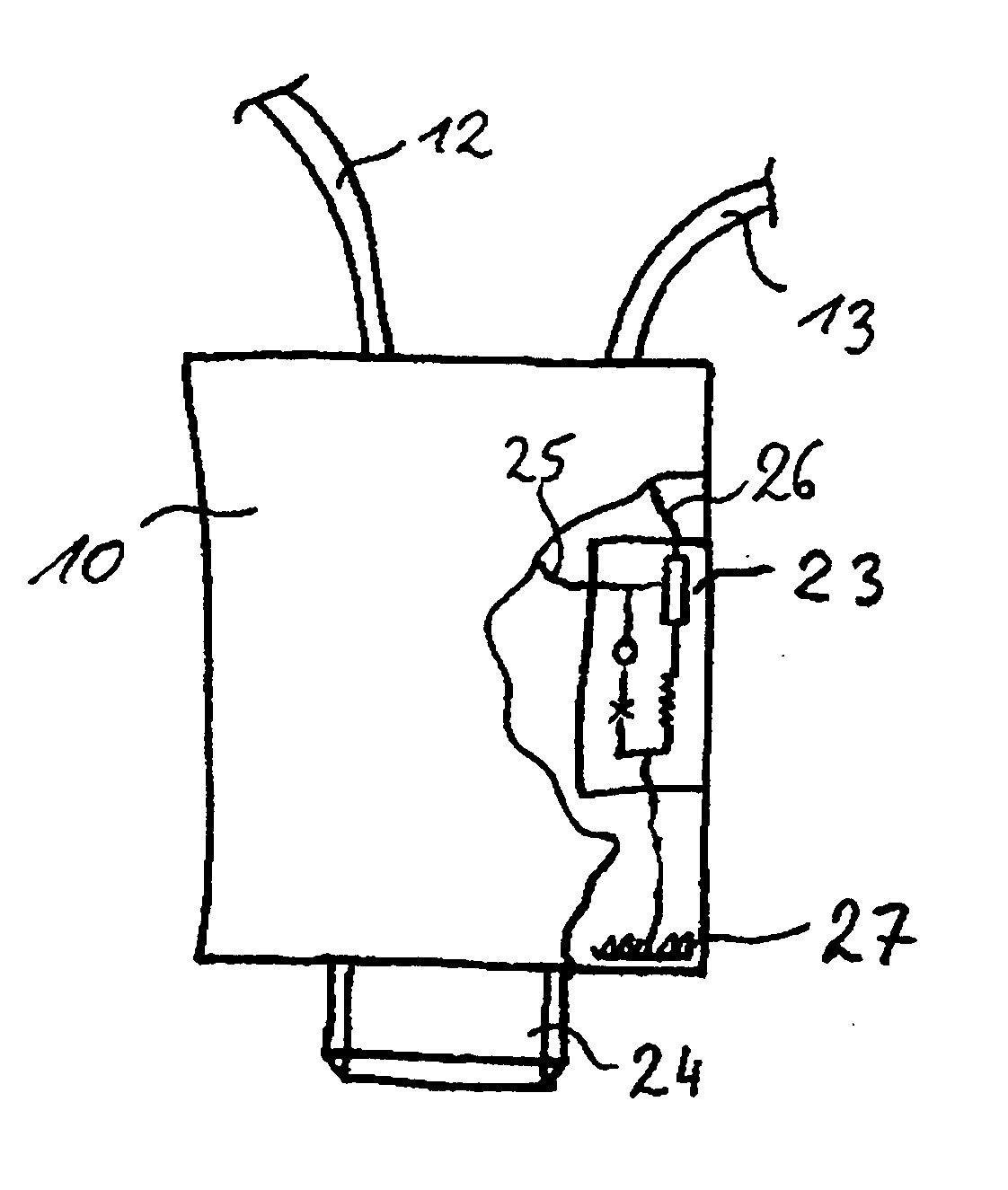
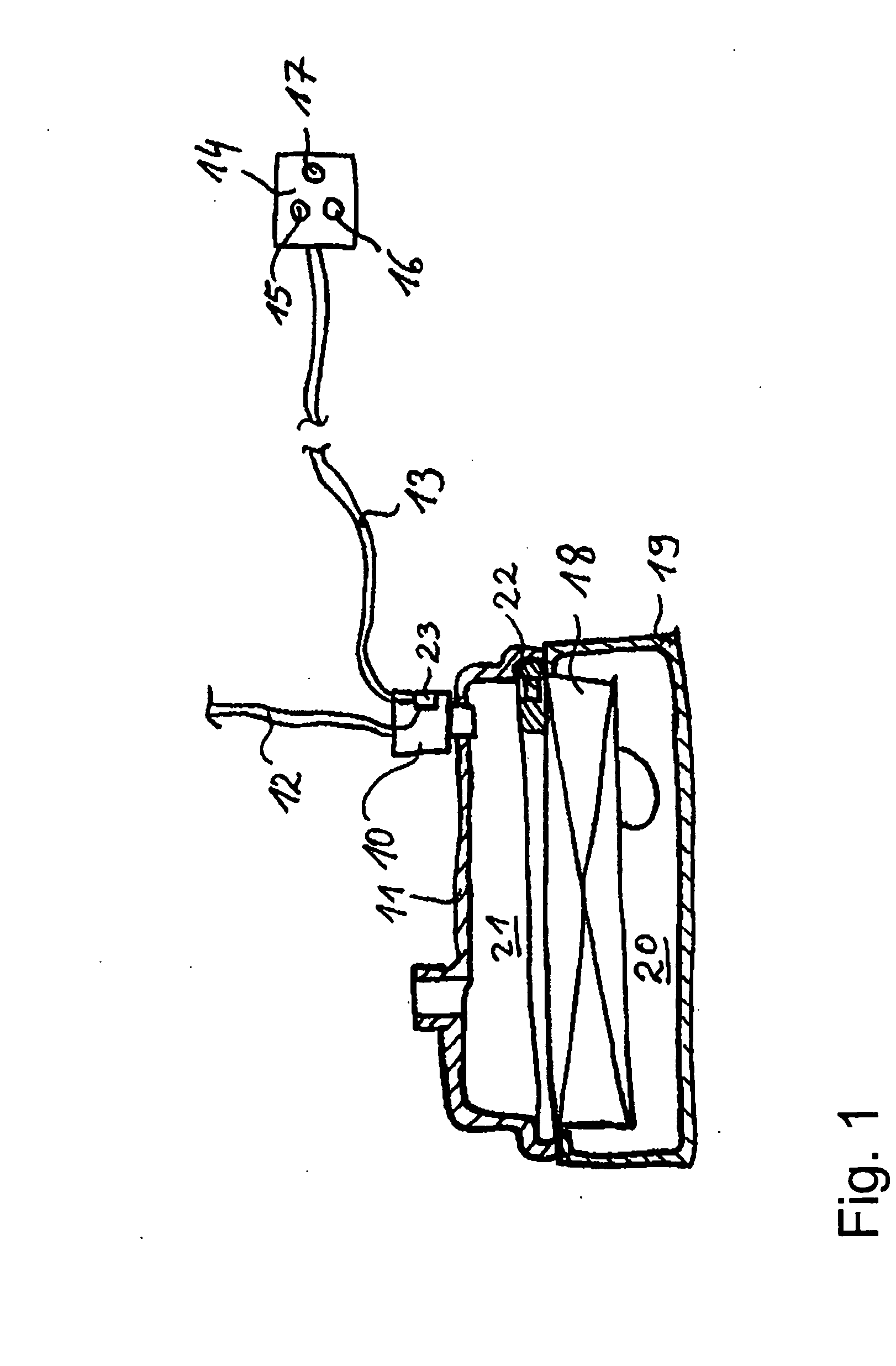
[0017]FIG. 1 schematically depicts an apparatus for monitoring consumable parts. The device comprises a maintenance switch 10, which is fixed to an upper housing part 11. The maintenance switch 10 is provided with a voltage supply 12. The voltage supply 12 is a line connecting a voltage or power source (not shown) to the maintenance switch 10. The maintenance switch further comprises a data line 13 which connects the maintenance switch 10 to a display 14. This data line 13 may be a cable, as shown. It is also possible, however, to use a radio or infrared-based data line.

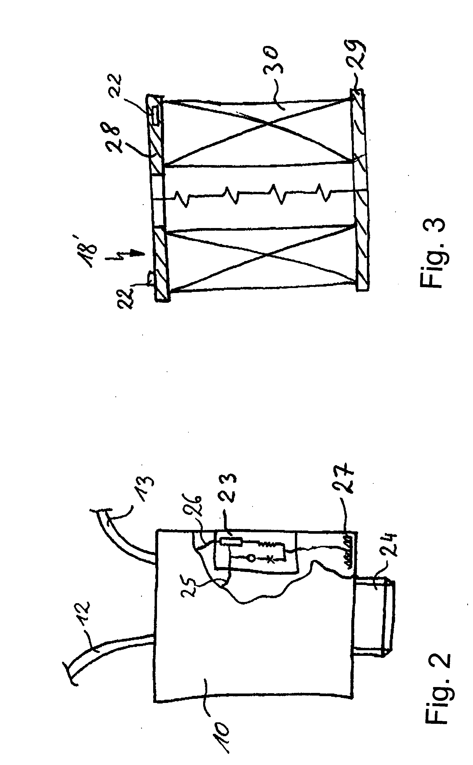
[0018] The display 14 in this example has a red diode 15, a green diode 16 and a yellow diode 17. The red and green diodes 15, 16 are each connected to the maintenance switch 10. These diodes 15, 16 indicate the monitored operational state of a filter element 18. The filter element 18 is disposed between the upper housing part 11 and a lower housing part 19, such that an unfiltered side 20 is sealingly separated fro...


PUM

PropertyMeasurementUnit
pressureaaaaaaaaaa
voltageaaaaaaaaaa
poweraaaaaaaaaa

Abstract

An apparatus for monitoring wearing or consumable parts 18, especially parts of internal combustion engines, in which monitoring verifies that the consumable part 18 is functioning and also ensures that a consumable part 18 conforming to specifications is used. The device has a maintenance switch 10, which is provided with a voltage supply 12 and a data line 13, which in turn is connected to a display 14, on which the monitoring result of the maintenance switch 10 is displayed. A chip 22 identifiable by a chip reader 23 is disposed in the consumable part 18. The chip reader 23 is integrated into the maintenance switch 10 and connected to the voltage supply 12 of the maintenance switch 10. This enables simple and cost-effective monitoring both of the functioning of the part and of the use of properly specified wearing or consumable parts.

Description

BACKGROUND OF THE INVENTION [0001] The present invention relates to an apparatus for monitoring the functioning of consumable parts, such as parts of an internal combustion engine which wear out and need to be replaced. [0002] The use of maintenance switches to monitor the functioning of filter elements is known in the art. For this purpose, the maintenance switch has a sensor that detects a specific functional characteristic of the filter, e.g., the pressure inside the filter housing. The maintenance switch has a voltage supply and a data line linked to a display. As soon as the filter element no longer functions as required, a corresponding signal is sent to the display via the data line. The display then indicates that the filter element must be replaced. The known maintenance switches, however, have the drawback that they do not check the filter element itself. Therefore, unsuitable or wrong filter elements can be installed, which may leave a downstream internal combustion engin...

Claims


Application Information

Patent Timeline
Patent Type & Authority Applications(United States)
IPC IPC(8): G01R27/08
CPCB01D46/0086B01D46/009F02M35/024B01D46/429
Inventor DWORATZEK, KLEMENSNGUYEN, DUC CUONG
Owner MANN HUMMEL GMBH
Why Eureka
Try Eureka