Eureka AIR delivers breakthrough ideas for toughest innovation challenges, trusted by R&D personnel around the world.

Optical assembly

Inactive Publication Date: 2006-08-31
COMMONWEALTH SCI & IND RES ORG
View PDF4 Cites 14 Cited by
  • Summary
  • Abstract
  • Description
  • Claims
  • Application Information

AI Technical Summary

Benefits of technology

[0013] Preferably, the transparent section is recessed into the enclosure. This helps to prevent airborne dust and other contaminants from reaching and building up on the transparent section. Preferably, the transparent section is located in an enclosed passage, and the light path through the transparent section passes along the length of the passage.
[0014] Preferably, when the test light beam is generated by a test source and detected by a test detector, the component which is located outside the enclosure is recessed. This prevents contamination from building up and affecting the performance of the external component. Preferably, the external component is located in a passage through which the test beam passes.
[0015] In a preferred aspect of the present invention, the optical assembly includes means for directing a flow of gas onto an external surface of the transparent section, to reduce build up of contaminants on the surface. Cleaning fluid may be introduced in the flow of gas.
[0016] In this preferred aspect of the present invention, the flow of gas directed at the external surface of the transparent section serves to substantially reduce build up of contaminants on the surface which would otherwise attenuate the emitted or received beam, and adding cleaning fluid to the flow cleans away any residue which has built up.
[0018] Preferably, the flow of gas is directed along the passage in which the external component of the test source-detector pair is located, and the flow is directed away from the external component and is incident on the transparent section. Furthermore, the flow of gas along the passage away from the test light source or detector also prevents build up of contaminants on the test source or detector.
[0020] In another embodiment, wherein the optical device is a detector, the detector can be arranged to detect both the test beam and a primary beam. When the light source for the primary beam is deactivated, and the light source for the test beam is activated, the detector receives light intensity from the primary beam, and vice versa. The advantage of this configuration is that it is simpler and requires fewer components.

Problems solved by technology

Industrial environments are often characterised by noise, vibration, temperature, and humidity, and devices used in industrial environments are exposed to fluids, solvents, airborne dust and vapour.
In this situation of optical sensing, elimination of interference from the industrial environment presents some particular challenges.
However, contamination still builds up on the outside of the transparent section, and may impede the passage of light into or out of the enclosure and adversely effect the measurement.
Particularly in unattended operation, there will always be uncertainty regarding the presence and / or the extent of contamination present and this may completely negate any benefit of using the instrument.

Method used


Image

  • Optical assembly
  • Optical assembly
  • Optical assembly

Examples


Embodiment Construction

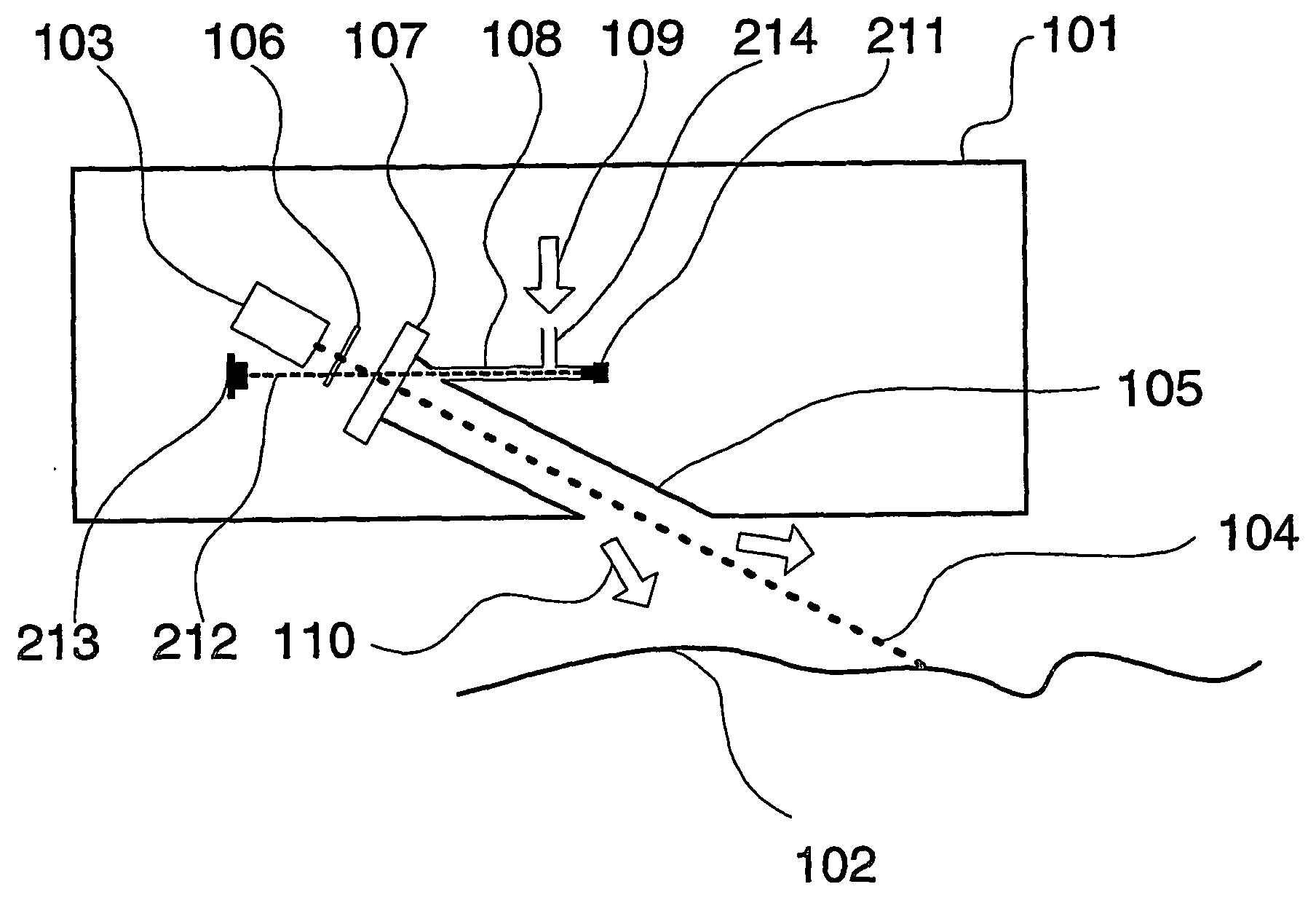
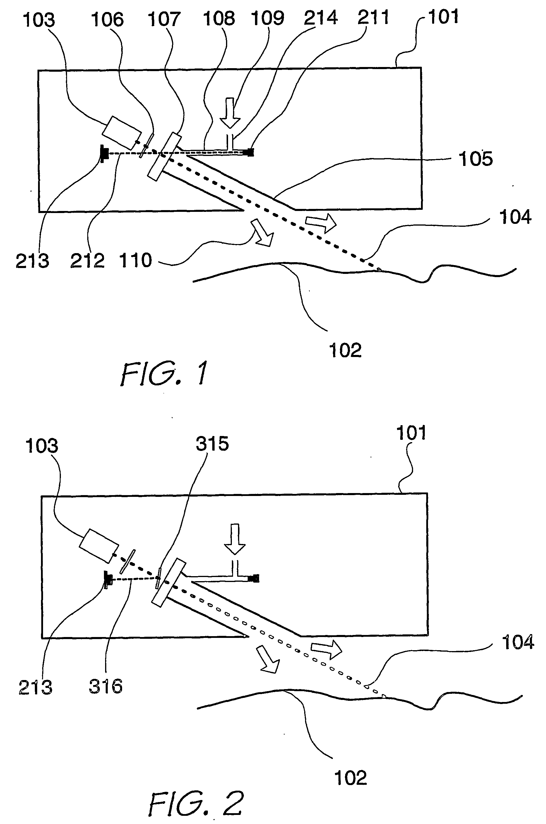
[0027]FIG. 1 illustrates a sealed enclosure 101 containing an optical device 103. The enclosure 101 is constructed to meet one of the most stringent requirements for electrical enclosures (e.g. IP67) including the requirement of being able to be totally immersed in water without leakage.

[0028] The enclosure 101 is positioned relative to a surface 102 to be measured. Optical device 103 represents, in one embodiment, an optical source e.g. LED or laser etc, or in another embodiment an optical detector. A light pathway 104 is shown to describe the motion of light either (a) from the source 103 to the surface 102 or vice versa in the case of the device 103 being a detector. The light beam travels along a passage 105 that recesses the window 107 into the enclosure 101. Other optical elements such as filters, polarisers, lenses etc may be located between the optical device 103 and the enclosure window 107. Sealing of the enclosure 101 is accomplished using a window 107 that is attached i...


PUM


Abstract

An optical assembly comprises an optical device (103); an enclosure (101) for containing the optical device (103), the enclosure (101) including a transparent section (107) to allow passage of a light beam (104) to or from the optical device (103); and means for measuring the attenuation of a test light beam (212) through the transparent section(107). Preferably, the optical assembly also comprises means for compensating for the measured amount of attenuation by adjusting a measurement or a characteristic of the optical device (103) or a related optical device to compensate for the measured amount of attenuation.

Description

FIELD OF THE INVENTION [0001] The present invention relates to an optical assembly, particularly for use in an industrial environment. The optical assembly preferably includes an enclosure for containing an optical device, the optical device typically being either a light source or a detector, and the enclosure includes a transparent window to allow light to enter or leave the enclosure to or from the optical device. [0002] Industrial environments are often characterised by noise, vibration, temperature, and humidity, and devices used in industrial environments are exposed to fluids, solvents, airborne dust and vapour. It is sometimes desirable to install sensitive equipment in such environments, for example, for the purposes of process monitoring. Depending on the mode of measurement, some or all of the industrial environmental factors may easily be screened or eliminated from interfering with the sensitive equipment. [0003] In particular, optical sensors are commonly used for proc...

Claims


Application Information

Patent Timeline
IPC IPC(8): G01N21/55G01N21/15G02B7/00
CPCG01N21/15G01N2021/151G01N2021/157G02B7/007
Inventor FARRANT, DAVID IANMARTIN, ALISTAIR SCOTTFREUND, CHRISTOPHER HAYESNETTERFIELD, ROGER PRYCEHERRMANN, JANREDFERN, DENIS LESLIE
Owner COMMONWEALTH SCI & IND RES ORG
Why Eureka
Eureka Blog
Learn More