
Highly bandwidth-efficient communications

Inactive Publication Date: 2006-08-31
CINGULAR WIRELESS II LLC
View PDF99 Cites 151 Cited by
  • Summary
  • Abstract
  • Description
  • Claims
  • Application Information

AI Technical Summary

Benefits of technology

[0050] In another aspect of the invention, the signals are transmitted in time division duplex format—e.g. a format in which base to remote signals are transmitted in different time periods than remote to base signals. In one embodiment of this aspect of the invention, a first plurality of received signal bursts separated by first-burst time-guard time-periods, are received by the receiving station. This is followed by transmission by the receiving station of a second plurality of transmitted signal bursts separated by second-burst time-guard time-periods. The first and second bursts are separated by an interburst time-guard time-period that is larger than either the first-burst time-guard time-period or the second-burst time-guard time-period. The interburst time-guard time-period is sufficiently large to reduce interference between signals received by the receiving station and signals transmitted by other receiving stations.
[0051] Another aspect of the invention is the application to wireless communications of the mathematical analogy that may exist between the representation of data that has been spectrally processed in accordance with certain multip

Problems solved by technology

However, when the spreading codes are not orthogonal (as is the case with spreading codes that are used in neighboring cells), cross modulation may result so that the data signals are not able to be precisely distinguished by simple despreading (i.e., despreading without code-nulling).

Method used


Image

  • Highly bandwidth-efficient communications
  • Highly bandwidth-efficient communications
  • Highly bandwidth-efficient communications

Examples


Embodiment Construction

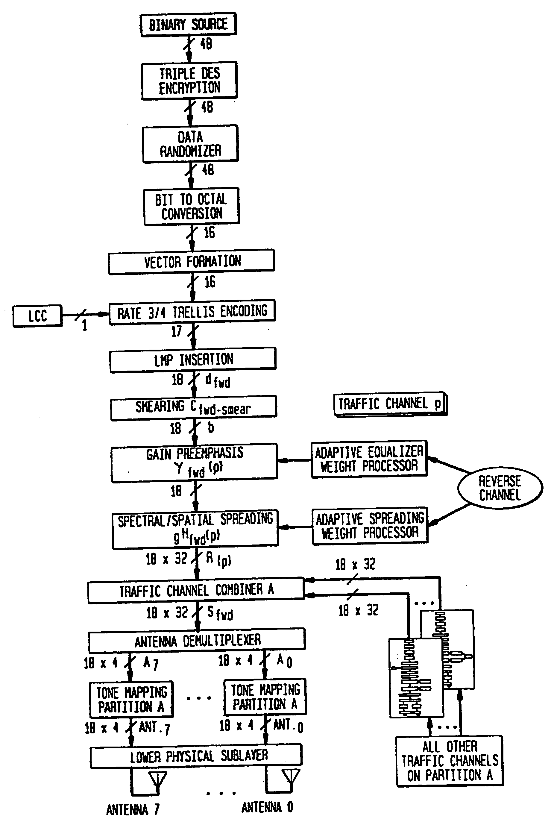
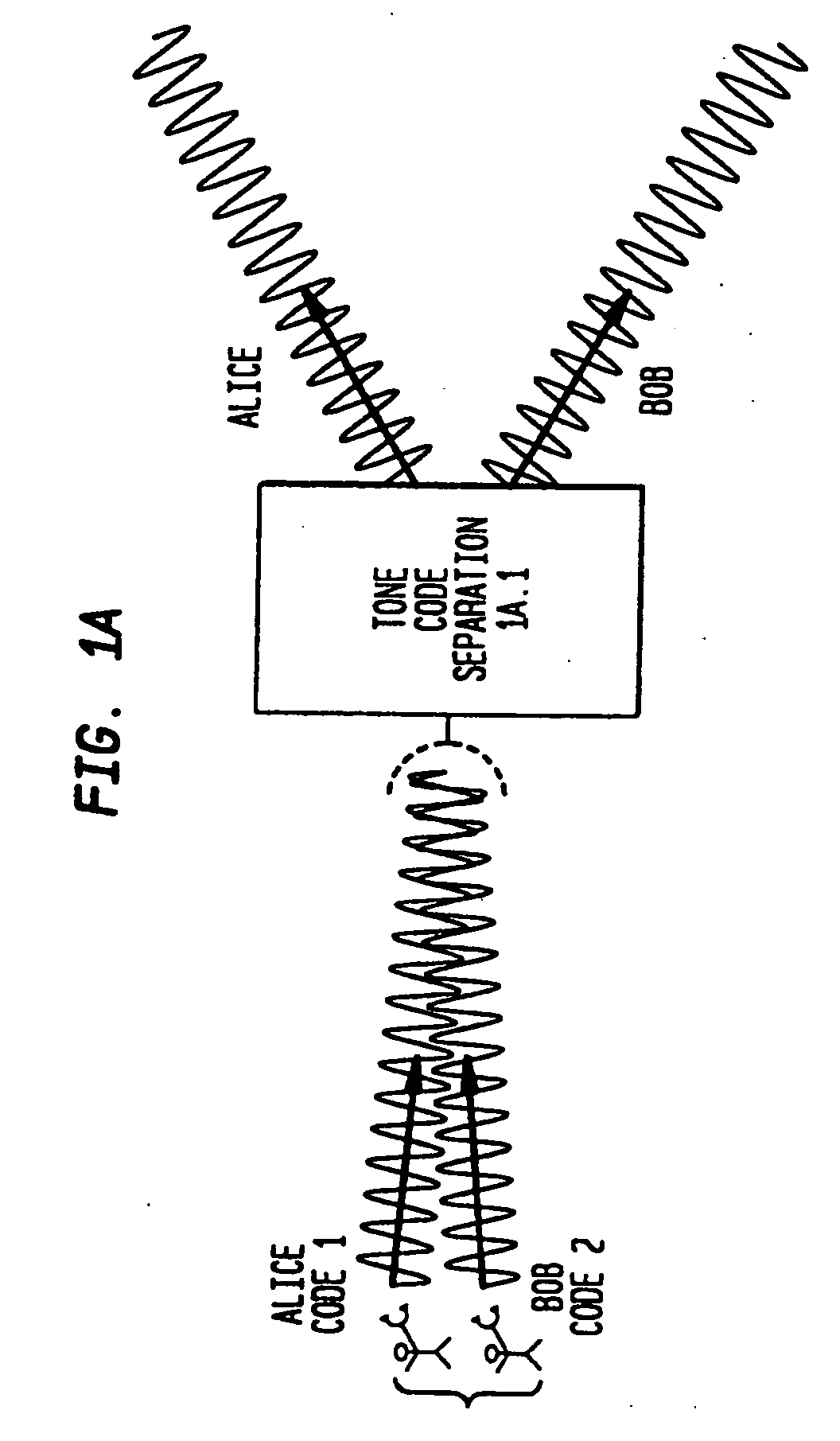
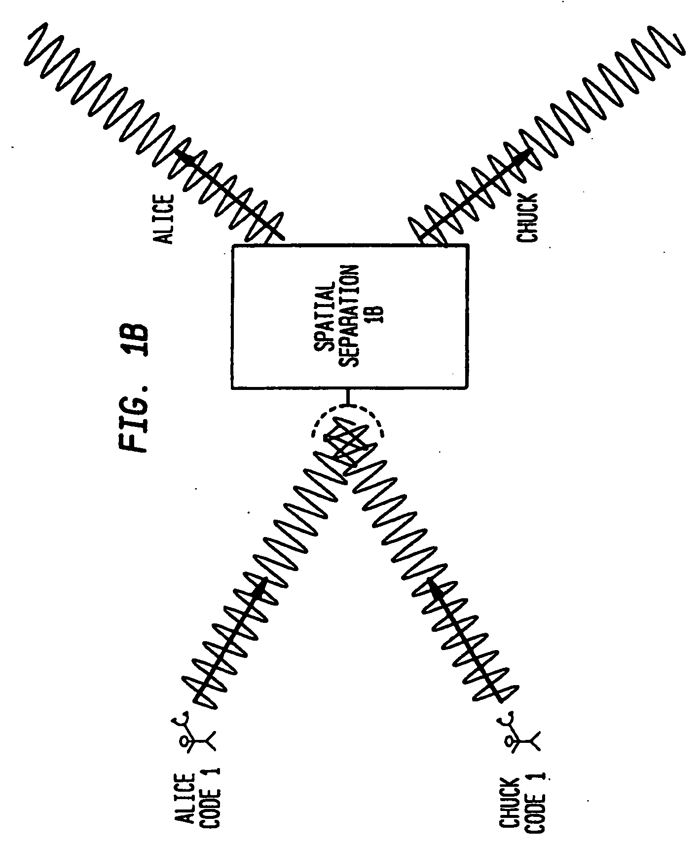
[0148] In what follows, aspects of the principles of the invention will be discussed in a tutorial illustrating an example of pure spectral diversity, an example of pure spatial diversity, and an example of mixed spectral and spatial diversity. This will be followed by a discussion of the invention in a high-level overview that will include an explanation of the waveform used in the practice of an aspect of this invention. This will be followed by a description of more specific “details of the invention,” and then by a detailed description of a “specific embodiment of the invention.”

High Level Overview of the Invention

Introduction

[0149] This invention is based, in part, on the realization that there is an analogy between the mathematical description of beams formed by multi-element adaptive, or phased, antenna arrays and the mathematical description of signals that are formatted according to certain multiple access schemes, such as the exemplary DMT-SC. Based on this realization...


PUM


Abstract

A discrete multitone stacked-carrier spread spectrum communication method is based on frequency domain spreading including multiplication of a baseband signal by a set of superimposed, or stacked, complex sinusoid carrier waves. In a preferred embodiment, the spreading involves energizing the bins of a large Fast Fourier transform (FFT). This provides a considerable savings in computational complexity for moderate output FFT sizes. Point-to-multipoint and multipoint-to-multipoint (nodeless) network topologies are possible. A code-nulling method is included for interference cancellation and enhanced signal separation by exploiting the spectral diversity of the various sources. The basic method may be extended to include multielement antenna array nulling methods for interference cancellation and enhanced signal separation using spatial separation. Such methods permit directive and retrodirective transmission systems that adapt or can be adapted to the radio environment. Such systems are compatible with bandwidth-on-demand and higher-order modulation formats and use advanced adaptation algorithms. In a specific embodiment the spectral and spatial components of the adaptive weights are calculated in a unified operation based on the mathematical analogy between the spectral and spatial descriptions of the airlink.

Description

CROSS-REFERENCES TO RELATED APPLICATIONS [0001] This is a continuation application of U.S. application Ser. No. 09 / 920,903, filed Aug. 3, 2001, which is a continuation application of U.S. application Ser. No. 08 / 993,721, filed Dec. 18, 1997, now U.S. Pat. No. 6,359,923, issued Mar. 19, 2002, which is a continuation application of U.S. application Ser. No. 08 / 804,619, filed Feb. 24, 1997, abandoned, each to which priority is claimed and each of which is herein incorporated by reference in its entirety.FIELD OF THE INVENTION [0002] This invention involves communications methods that make very efficient use of available spectral bandwidth by a combination of multiple access techniques. BACKGROUND OF THE INVENTION [0003] Communication systems that operate over limited spectral bandwidths must make highly efficient use of the scarce bandwidth resource to provide acceptable service to a large population of users. Examples of such communications systems that deal with high user demand and ...

Claims


Application Information

Patent Timeline
IPC IPC(8): H04B1/707H04K1/10H04J11/00H04B1/69H04B1/692H04B1/7107H04B7/005H04B7/04H04B7/08H04L5/02H04W16/14H04W88/08
CPCH04B1/69H04B1/692H04B1/707H04B1/7107H04B7/04H04B2201/70702H04L5/0021H04L5/0026H04L5/0048H04L5/026H04L25/0228H04L25/03019H04L27/186H04L27/3416H04L2025/03414H04L2025/03426H04W16/14H04W88/08
Inventor AGEE, BRIAN G.BROMBERG, MATTHEWGERLACH, DEREKGIBBONS, DAVIDGOLDEN, JAMES TIMOTHYHO, MINNIEHOOLE, ELLIOTTJESSE, MARYMAXWELL, ROBERT LEEMECHALEY, ROBERT G. JR.NAISH, ROBERT RAYNIX, DAVID J.RYAN, DAVID JAMESSTEPHENSON, DAVID
Owner CINGULAR WIRELESS II LLC
Learn More