Method and apparatus for making and displaying measurements based upon multiple 3D rangefinder data sets

a technology of 3d rangefinder and data sets, applied in the field of 3d rangefinder processing technology, can solve the problems of difficult identification and specifying the correct features of interest for measurement by users, complicated and often confusing display to users, etc., and achieve the effect of effective making and displaying measurements and improving application services

Inactive Publication Date: 2006-08-31
UATC LLC
View PDF28 Cites 84 Cited by
  • Summary
  • Abstract
  • Description
  • Claims
  • Application Information

AI Technical Summary

Benefits of technology

[0020] The present invention and its various embodiments seek to address at least some of the above needs and problems while attempting to deliver one or more of the above advantages. Further, the present invention provides a number of embodiments that seek to allow a user to more effectively make and display measurements based upon a

Problems solved by technology

In conventional methods, the merger of multiple 3D data sets into a single 3D display with many thousands or millions of data points may create a very compl

Method used


Image

  • Method and apparatus for making and displaying measurements based upon multiple 3D rangefinder data sets
  • Method and apparatus for making and displaying measurements based upon multiple 3D rangefinder data sets
  • Method and apparatus for making and displaying measurements based upon multiple 3D rangefinder data sets

Examples


Embodiment Construction

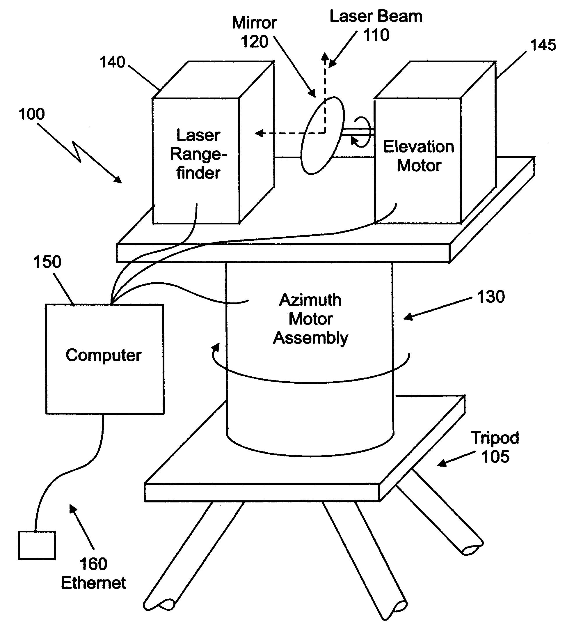
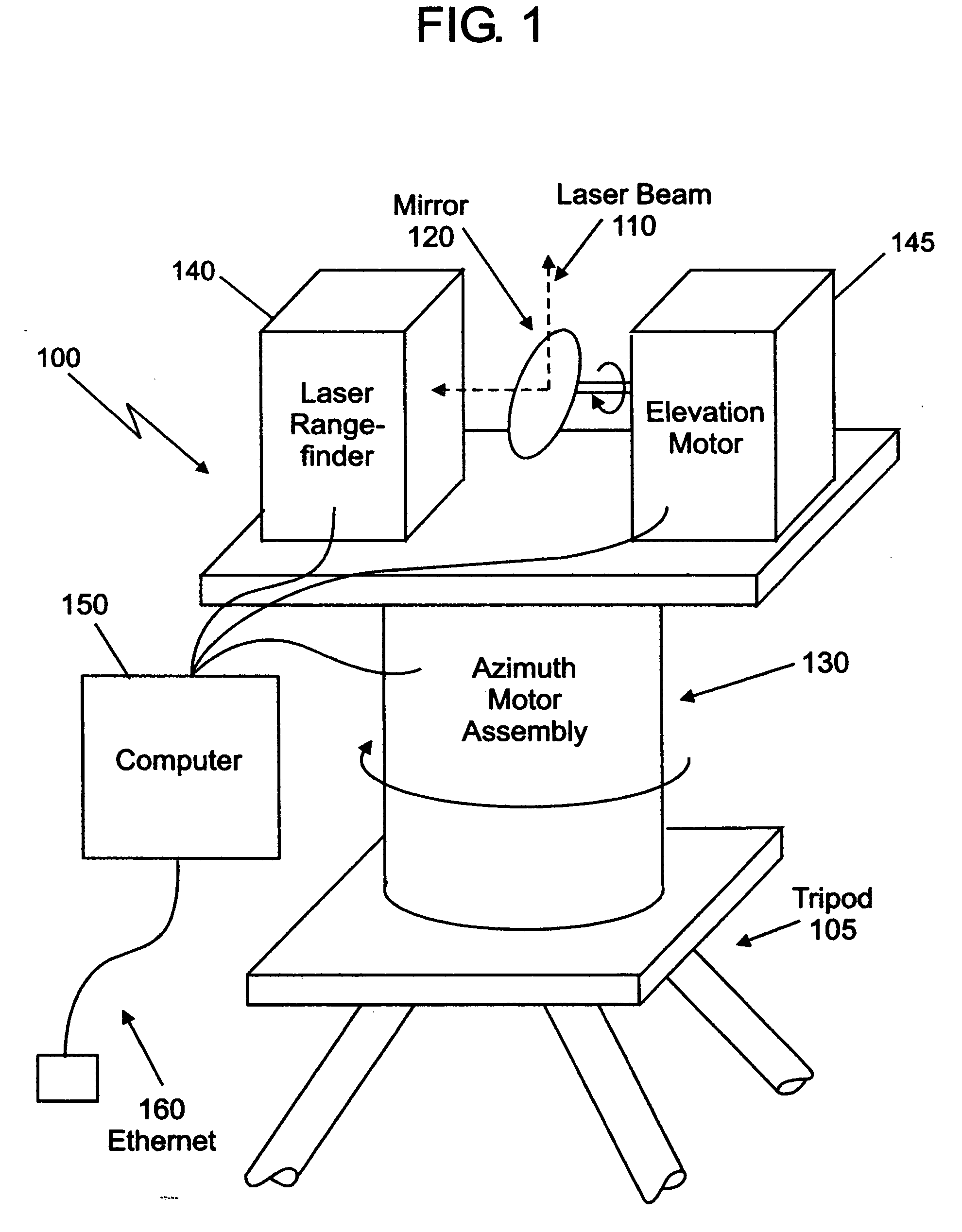
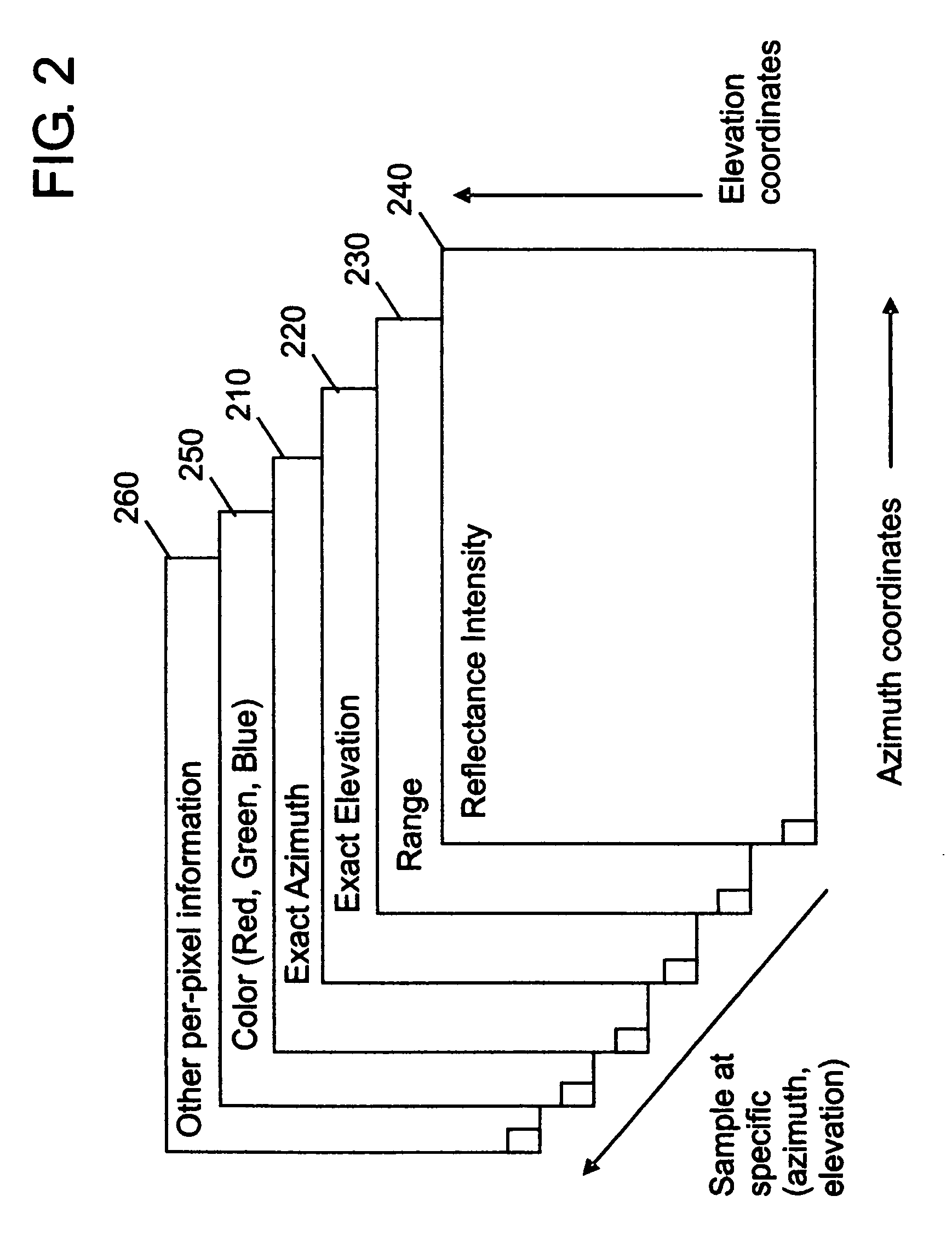
[0036] The present invention now will be described more fully hereinafter with reference to the accompanying illustrative figures, in which various embodiments of the invention are shown. This invention may, however, be embodied in many different forms and should not be construed as limited to the embodiments set forth herein. Rather, these embodiments are provided so that this disclosure of the present invention will be thorough and complete, and will fully teach and describe the invention to those skilled in the art. Although specific terms are employed herein, they are used in a generic and descriptive sense only and not for purposes of limiting the scope of the present invention as defined by the attached claims in any way. Some terminology may be defined herein and used to describe forthcoming embodiments of the present invention, in order to teach the present invention to those skilled in the art. Terms not described explicitly in this disclosure should be construed as they wo...


PUM


Abstract

A method, computer program product, and apparatus for making and displaying measurements based upon multiple 3D range data sets obtained using a 3D rangefinder device. At least a first and a second 3D range data sets are provided. A 3D transformation is computed therebetween. The first 3D range data set is represented as a first displayed image and the second 3D range data set is represented as a second displayed image. At least two features are identified within the first and second displayed images respectively. A measurement is computed based on at least the first feature and the second feature utilizing the 3D transformation between the first and second 3D range data sets. The computed measurement may be displayed within at least one of the first displayed image and the second displayed image.

Description

CROSS REFERENCE TO RELATED APPLICATIONS [0001] This patent application claims the benefit of U.S. provisional application Ser. No. 60 / 652,208 filed Feb. 11, 2005, the entire contents of which are incorporated by reference herein.FIELD OF THE INVENTION [0002] The present invention relates to 3D rangefinder processing technology generally, and more particularly relates to methods, computer program products, and apparatus for making and displaying measurements based upon at least two 3D rangefinder data sets. BACKGROUND OF THE INVENTION [0003] A rangefinder is a device for measuring the range from the device to some physical surface. A laser rangefinder can be one of many known types of rangefinders. Laser rangefinders are sometimes known as LIDAR (Light Detection and Ranging) or LADAR (Laser Detection and Ranging) systems. Laser rangefinders use a variety of techniques to measure the range from the apparatus to a surface from which the laser beam is reflected. A typical apparatus may ...

Claims


Application Information

Patent Timeline
IPC IPC(8): G06K9/46
CPCG01S7/4817G01S7/51G01S17/42
Inventor ENGLAND, JAMES N.HELSER, ARON T.ELGIN, BENJAMIN C.HOLLOWAY, RICHARD L.
Owner UATC LLC
Why Eureka
Try Eureka