Fiber optic receptacle and plug assembly including alignment sleeve insert

a fiber optic and plug assembly technology, applied in the field of fiber optic receptacle and plug assembly, can solve the problems of inability to meet the high tensile load required for fttx installation, inability to meet the high tensile load of current smaller sized assemblies, and inability to meet the high tensile load of fttx installation, etc., to achieve the effect of convenient ma

Active Publication Date: 2006-08-31
CORNING OPTICAL COMM LLC
View PDF27 Cites 105 Cited by
  • Summary
  • Abstract
  • Description
  • Claims
  • Application Information

AI Technical Summary

Benefits of technology

[0010] In one aspect, the present invention provides various embodiments of fiber optic receptacle and plug assemblies adapted to receive like ferrule configurations. Thus, the present invention provides fiber optic receptacle and plug assemblies designed to readily mate any like number of optical fibers via the use of a connector port disposed within a wall of an enclosure. The present invention further provides smaller sized (i.e., low volume) fiber optic receptacles designed to be secured within connector ports or similar structures of an enclosure, while providing strain relief against drop cable-pulling forces of up to about 600 lbs.
[0011] In another aspect, the present invention provides a fiber optic receptacle and plug assembly comprising a fiber optic receptacle adapted to be mounted within a connector port of a network connection terminal and a corresponding fiber optic plug mounted upon an end of a fiber optic cable. The fiber optic receptacle and the fiber optic plug comprise complimentary alignment and keying features that allow the fiber optic receptacle to receive only a fiber optic plug of like ferrule configuration. The fiber optic plug engages a corresponding receptacle within a connector port disposed within a wall of a network connection terminal or other enclosure. The alignment and keying features of the fiber optic receptacle and plug assembly allow non-centric positions of at least one ferrule and radial alignment of the ferrule. The fiber optic receptacle defines an interior cavity for receiving and housing an alignment sleeve insert that includes an alignment sleeve holder defining one or more openings for receiving an alignment sleeve. The alignment sleeve insert is relatively shallow, thus minimizing the depth of the receptacle. The receptacle defines a keying and alignment feature within its interior cavity that is received within a keying and alignment slot defined by the alignment sleeve holder. The keying and alignment feature defined by the receptacle also corresponds to a plug insert of a corresponding fiber optic plug. The receptacle further comprises a shoulder that is secured against a wall of the connection terminal in order to provide strain relief. In an alternative embodiment, the alignment sleeve insert is a molded feature of the receptacle.

Problems solved by technology

In addition to requiring the use of different fiber optic receptacles and plugs based upon the specific type of optical connector, conventional receptacle and plug assemblies are relatively large in size.
Current smaller sized assemblies, however, are not able to satisfy the high tensile loads required for FTTx installations, including for example the 600 lbs. drop cable pull test requirement.
Exposure to adverse environmental conditions is also a significant concern since current network plans suggest that receptacles may remain unoccupied (without a mated plug) for an extended period of time due to initial service (also referred to as “take rates”) being less than total capacity.
As yet however, there is an unresolved need for a compact, yet sufficiently robust fiber optic receptacle that is configured to receive only a fiber optic plug having the same type of optical fiber connector.

Method used


Image

  • Fiber optic receptacle and plug assembly including alignment sleeve insert
  • Fiber optic receptacle and plug assembly including alignment sleeve insert
  • Fiber optic receptacle and plug assembly including alignment sleeve insert

Examples


Embodiment Construction

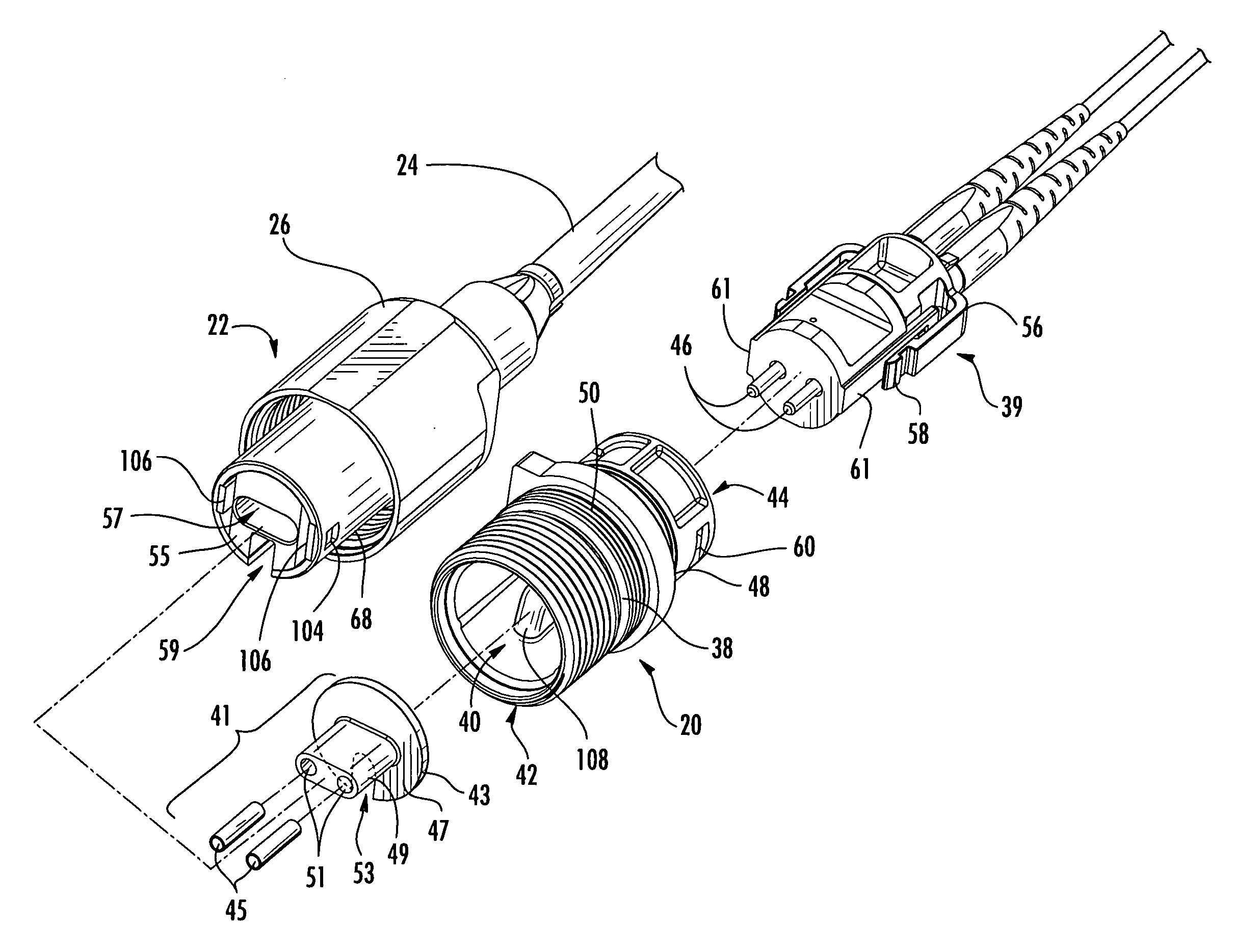
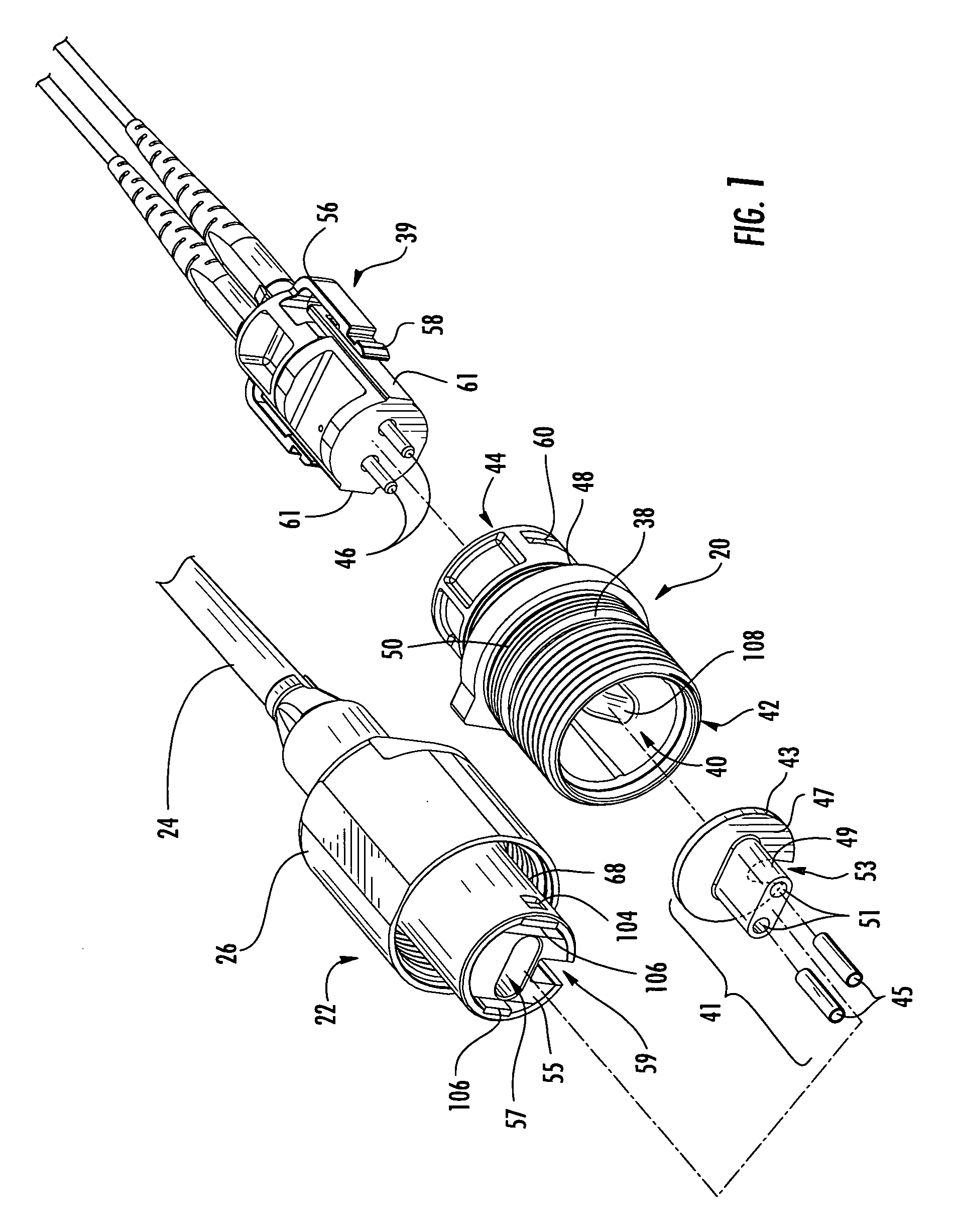
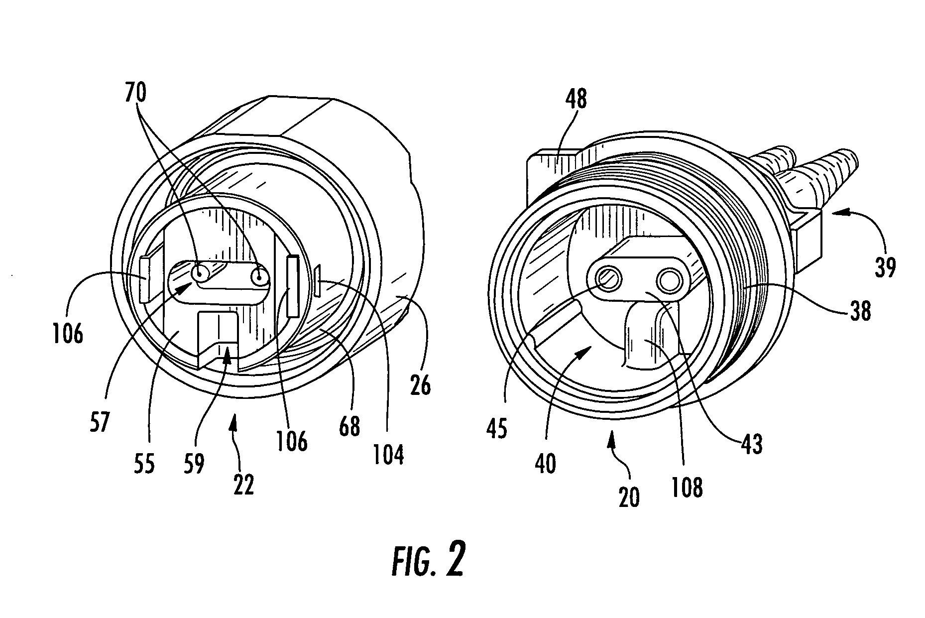
[0031] Reference will now be made in detail to the present preferred embodiments of the invention, examples of which are illustrated in the accompanying drawings. Whenever possible, the same reference numerals will be used throughout the drawings to refer to the same or like parts. Although specific, fiber optic receptacle and plug assemblies for interconnecting optical fibers are shown throughout the figures, it should be understood that the receptacle and plug assemblies described and shown herein may be modified in certain respects, while still including an alignment sleeve insert with alignment and keying features in accordance with the intended scope of the present invention.

[0032] In the various embodiments described below, the present invention comprises fiber optic receptacle and plug assemblies for interconnecting optical fibers within an optical communications network. The receptacle portion of each assembly is designed such that it may be mounted in a wall of an enclosur...


PUM


Abstract

A fiber optic receptacle and plug assembly includes a fiber optic receptacle adapted to be mounted within a connector port of a network connection terminal and a fiber optic plug mounted upon an end of a fiber optic cable, wherein the fiber optic receptacle and the fiber optic plug comprise complimentary alignment and keying features that allow the fiber optic receptacle to receive only a fiber optic plug of like ferrule configuration. The fiber optic receptacle includes an alignment sleeve insert operable for receiving and optically connecting at least one receptacle ferrule and at least one opposing plug ferrule. The receptacle is suitable for use in enclosures requiring a minimal receptacle penetration depth, wherein the fiber optic receptacle comprises a shoulder that is secured against an inner wall of the enclosure to provide strain relief against cable-pulling forces of up to about 600 lbs.

Description

CROSS-REFERENCE TO RELATED APPLICATIONS [0001] This application is a continuation-in-part of U.S. application Ser. No. 11 / 066,986 filed on Feb. 25, 2005 and entitled “FIBER OPTIC RECEPTACLE AND PLUG ASSEMBLIES WITH ALIGNMENT AND KEYING FEATURES,” the contents of which are hereby incorporated by reference.BACKGROUND OF THE INVENTION [0002] 1. Field of the Invention [0003] The present invention relates generally to assemblies for interconnecting optical fibers, and more specifically, to fiber optic receptacle and plug assemblies including an alignment sleeve insert with alignment and keying features for interconnecting optical fibers within a fiber optic communications network. [0004] 2. Technical Background [0005] Optical fiber is increasingly being used for a variety of broadband applications including voice, video and data transmissions. As a result, fiber optic communications networks include a number of interconnection points at which optical fibers are interconnected with other ...

Claims


Application Information

Patent Timeline
Patent Type & Authority Applications(United States)
IPC IPC(8): G02B6/36
CPCG02B6/3825G02B6/3831G02B6/3849G02B6/3869G02B6/3874G02B6/3878G02B6/3879G02B6/3887G02B6/3893G02B6/3894G02B6/4465G02B6/3888G02B6/38875G02B6/545
Inventor THEUERKORN, THOMAS
Owner CORNING OPTICAL COMM LLC
Why Eureka
Try Eureka