
Method and apparatus for controlling panning/tilting motor of monitoring camera

Active Publication Date: 2006-08-31
HANWHA TECHWIN CO LTD
View PDF4 Cites 10 Cited by
  • Summary
  • Abstract
  • Description
  • Claims
  • Application Information

AI Technical Summary

Benefits of technology

[0041] Preferably, the method further comprises, if each section is not the section 2, 4 or 6 in the step of determining the section, determining whether the value X is smaller than the value Y, and if the value X is smaller than the value Y, adding each offset value to a value of a table address having the most approximate value to the ratio value with reference to the second table to calculate an elect

Problems solved by technology

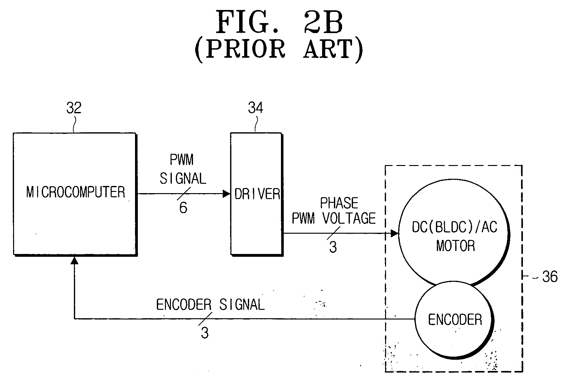
First, since there is no feedback signal corresponding to the position of the motor, position information is wrong when the motor is out of step.
Specifically, since the monitoring camera has to continuously operate for the purpose of the product and is mainly installed outdoors, the motor is prone to stepping out due to vibration, wind or the like.
Hence, the open loop control system using the stepping motor of FIG. 2A in the monitoring camera has the cost advantage, but lacks a desired level of position accuracy.
In addition, since the accuracy of the position control is influenced by resolution of the encoder, an expensive encoder of a high resolution is needed for more accurate position control.

Method used


Image

  • Method and apparatus for controlling panning/tilting motor of monitoring camera
  • Method and apparatus for controlling panning/tilting motor of monitoring camera
  • Method and apparatus for controlling panning/tilting motor of monitoring camera

Examples


Embodiment Construction

[0053] Certain embodiments of the present invention will be described in greater detail with reference to the accompanying drawings.

[0054] In the following description, same drawing reference numerals are used for the same elements throughout the drawings. Well-known functions or constructions are not described in detail since they would obscure the invention in unnecessary detail.

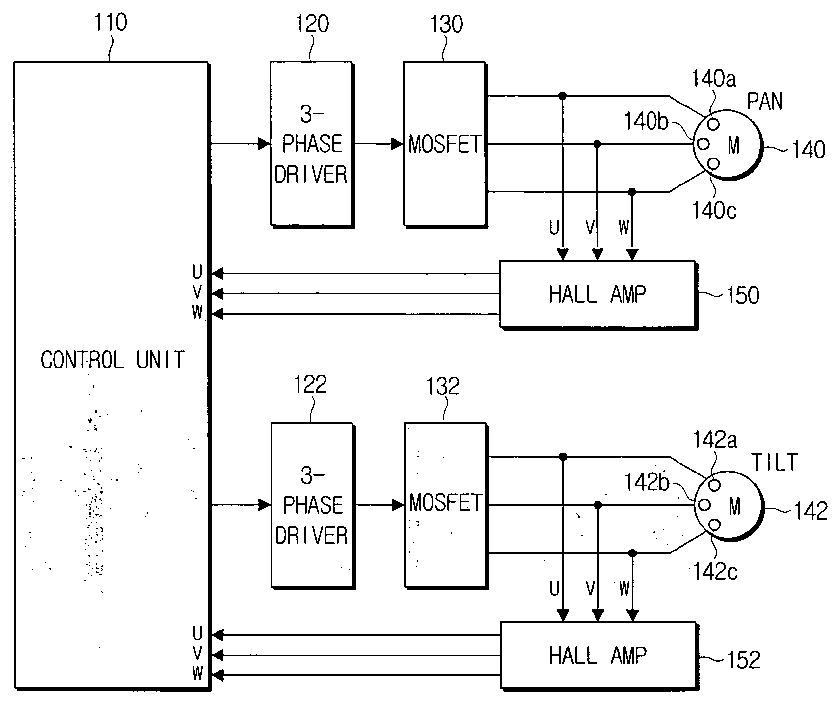
[0055]FIG. 3 is a block diagram of a panning / tilting motor control system using a BLDC motor according to the present invention. As shown in FIG. 3, the panning / tilting motor control system includes BLDC motors 140 and 142 each having three hall sensors (e.g., 140a, 140b, 140c and 142a, 142b, 142c (respectively), a control unit 110 for outputting six PWM pulses to drive the BLDC motors 140 and 142 and for receiving the voltages of the hall sensors 140a, 140b, 140c, and 142a, 142b, 142c, respectively, of the BLDC motors 140 and 142 to execute the position control operation, 3-phase motor drivers 120 and 1...


PUM


Abstract

A method and apparatus for controlling a panning / tilting motor of a monitoring camera is disclosed. The position or speed of the motor is controlled based on the output of a hall sensor built in the motor without any position detection device such as encoder, so that the closed loop control of the panning / tilting motor is accurately performed, and the position coordinate of the panning / tilting motor is not distorted when the motor is out of step.

Description

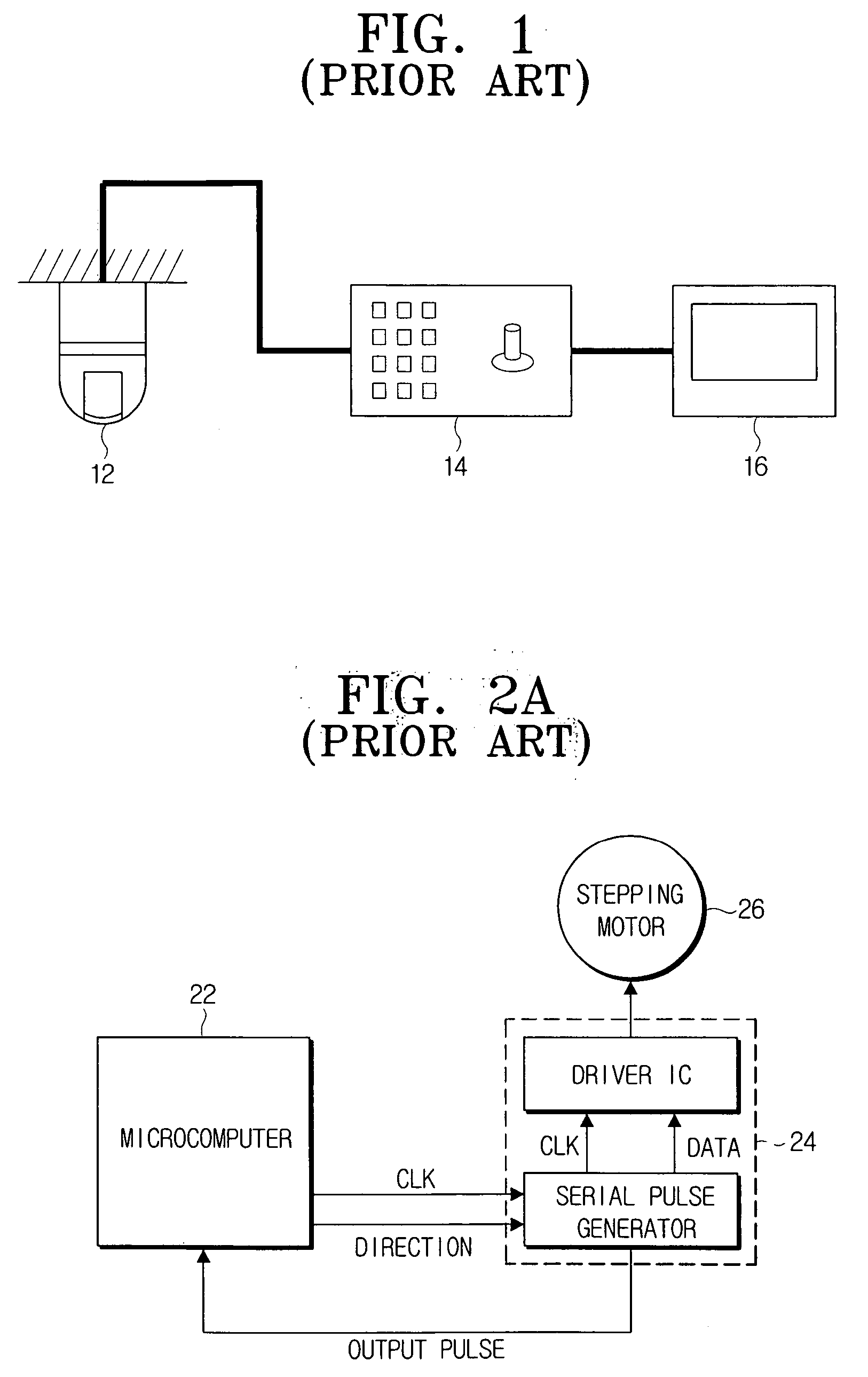
[0001] This application claims the benefit under 35 U.S.C. § 119(a) from Korean Patent Application No. 2005-16795, filed on Feb. 28, 2005, in the Korean Intellectual Property Office, the disclosure of which is incorporated herein by reference. BACKGROUND OF THE INVENTION [0002] 1. Field of the Invention [0003] The present invention relates to a method for controlling a panning / tilting motor of a monitoring camera. More particularly, the present invention relates to a method for controlling a panning / tilting motor in a closed loop using a brushless DC (BLDC) motor without employing a position detection device such as an encoder. [0004] 2. Description of the Related Art [0005] A speed dome camera which is an example of a closed-circuit TV (hereinafter referred to as “CCTV”) monitoring system is a camera that detects motion in a monitoring area and moves in horizontal and vertical directions through a panning / tilting function. The camera is mounted in a hemispheric or spherical housing...

Claims


Application Information

Patent Timeline
IPC IPC(8): G03B17/00
CPCG03B17/56G03B37/00G03B17/561H04N7/18
Inventor KIM, HAK-JEPARK, HYE-YOUNG
Owner HANWHA TECHWIN CO LTD
Learn More