Protective drainage wraps

a technology of drainage wraps and protective wraps, applied in the field of protective wraps, can solve problems such as moisture build-up

Inactive Publication Date: 2006-08-31
PACTIV CORP
View PDF47 Cites 20 Cited by
  • Summary
  • Abstract
  • Description
  • Claims
  • Application Information

AI Technical Summary

Benefits of technology

[0009] According to one method, a protective wrap to be used in a building is provided. The protective wrap includes a polymeric spunbonded portion and a plurality of fibers, filaments, tapes or yarn. The polymeric spunbonded portion is adapted to allow water vapor to flow therethrough. The plurality of fibers, filaments, tapes or yarn is attached to the polymeric spunbonded portion and forms a plurality of channels to assist in facilitating a drainage path for draining liquid moisture from the protective drainage wrap. At least one framing member is provided. The protective wrap is installed over at least one of the framing members.
[0010] According to another method, a protective wrap to be used in a building is provided. The protective wrap includes a polymeric spunbonded portion and a plurality of fibers, filaments, tapes or yarn. The polymeric spunbonded portion is adapted to allow water vapor to flow therethrough. The plurality of fibers, filaments, tapes or yarn is attached to the polymeric spunbonded portion and forms a plurality of channels to assist in facilitating a drainage path for draining liquid moisture from the protective drainage wrap. A sheathing is provided and the protective wrap is installed over the sheathing.
[0011] According to one method of forming a protective drainage wrap, the method comprises providing a polymeric spunbonded portion being adapted to allow water vapor to flow therethrough. A plurality of fibers, filaments, tapes or yarn is attached to the polymeric spunbonded portion and forms a plurality of channels to assist in facilitating a drainage path for draining liquid moisture from the protective drainage wrap.

Problems solved by technology

Air infiltration may occur in typical construction through, among other places, sheathing seams and cracks around windows and doors.
Moisture build-up can occur externally in the wall cavity from, for example, leaking exterior finishes or coverings, and cracks around windows and doors.

Method used


Image

  • Protective drainage wraps
  • Protective drainage wraps
  • Protective drainage wraps

Examples


Embodiment Construction

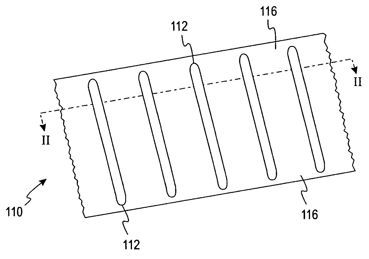
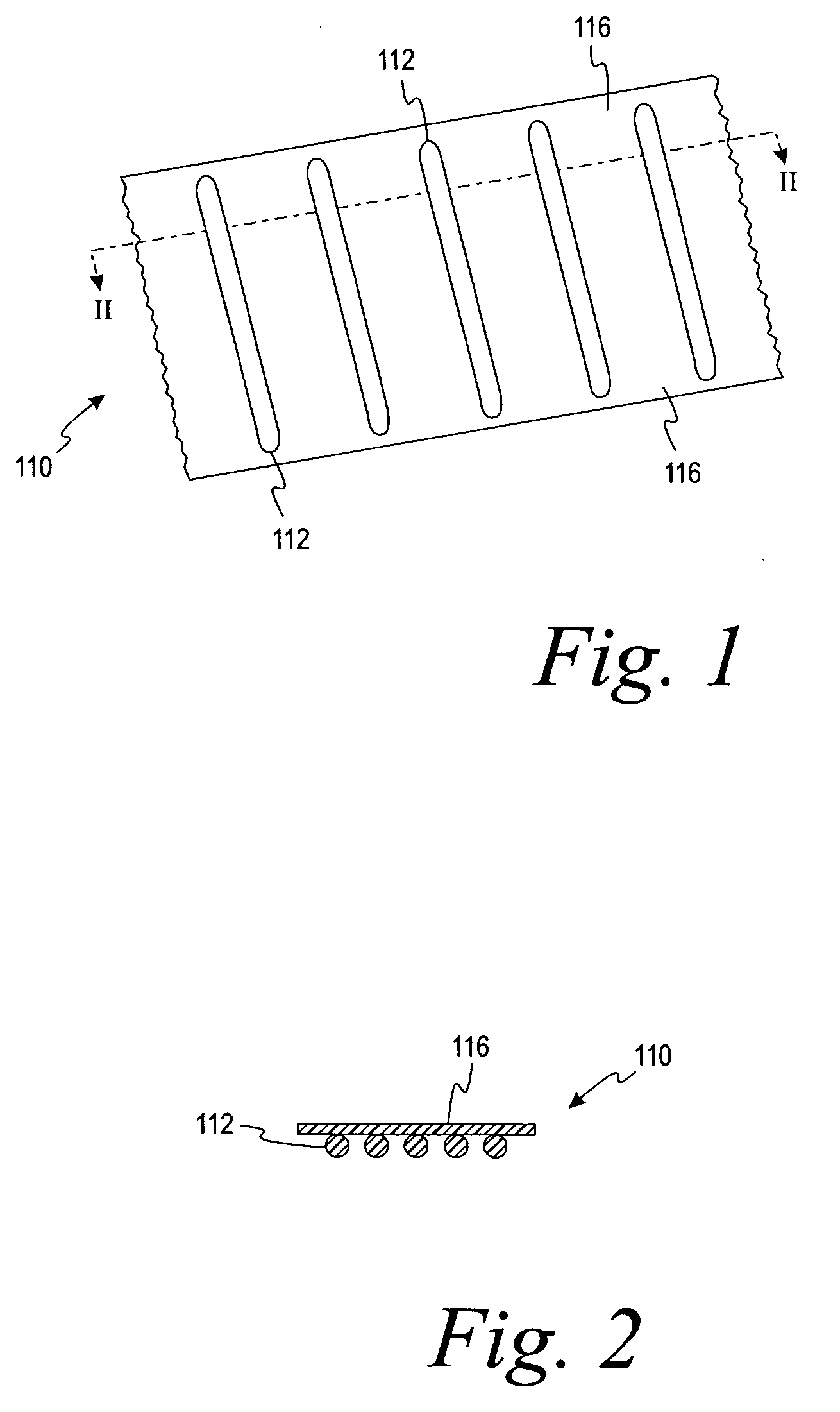
[0019] Turning now to the drawings and referring initially to FIGS. 1 and 2, a protective drainage wrap 110 according to one embodiment is shown. The protective wraps of the present invention, including protective wrap 110, are adapted to be attached over sheathing or framing members. The protective wraps are typically covered by an exterior covering such as siding, brick, stone, masonry, stucco (e.g., synthetic or cementitious) or concrete veneer.

[0020] The protective wrap 110 of FIGS. 1 and 2 comprises a plurality of fibers, filaments, tapes or yarn 112 and a polymeric spunbonded portion 116. The plurality of fibers, filaments, tapes or yarn of the protective wrap assists in providing an improved traverse direction (TD) strength. A desirable TD strength and machine direction (MD) strength assists in inhibiting or preventing tears and / or fraying that may be caused during installation. These tears and / or fraying may be caused by, for example, nails or staples during the installatio...


PUM

PropertyMeasurementUnit
thicknessaaaaaaaaaa
thicknessaaaaaaaaaa
thicknessaaaaaaaaaa

Abstract

A protective drainage wrap comprises a polymeric spunbonded portion being adapted to allow water vapor to flow therethrough and a plurality of fibers, filaments, tapes or yarn being attached to the polymeric spunbonded portion. The plurality of fibers, filaments, tapes or yarn forms a plurality of channels to assist in forming a drainage path for draining liquid moisture from the protective drainage wrap.

Description

CROSS-REFERENCE TO RELATED APPLICATIONS [0001] This application is a continuation-in-part of application Ser. No. 10 / 869,333 filed on Jun. 16, 2004, which is entitled “Method for Producing Protective Drainage Wraps”; application Ser. No. 10 / 869,333 is a division of application Ser. No. 10 / 255,273 filed on Sep. 26, 2002 and issued as U.S. Pat. No. 6,869,901; application Ser. No. 10 / 255,273 is a continuation-in-part of U.S. application Ser. No. 09 / 788,776 filed on Feb. 20, 2001, and issued as U.S. Pat. No. 6,550,212. Application Ser. Nos. 10 / 869,333; 10 / 255,273; and 09 / 788,776 are all incorporated herein by reference in its entirety.FIELD OF THE INVENTION [0002] The present invention relates generally to protective wraps that are used to protect against air infiltration and moisture build-up in buildings. Specifically, the protective wraps of the present invention include a polymeric spunbonded portion being attached to a plurality of fibers, filaments, tapes or yarn. BACKGROUND OF TH...

Claims


Application Information

Patent Timeline
Patent Type & Authority Applications(United States)
IPC IPC(8): E04B1/70D03D15/00E04C1/00B32B5/02B32B5/26B32B27/04B32B27/12D06N7/00E04B1/62E04F13/08
CPCB32B3/16D06N2209/123B32B5/08B32B5/12B32B5/26B32B21/02B32B21/10B32B2262/0253B32B2262/0276B32B2307/7246B32B2307/7265B32B2419/00D03D15/00D03D15/0027D03D15/0088D10B2321/02D10B2321/021D10B2321/022D10B2331/02D10B2331/04D10B2401/10D10B2505/00D10B2505/20E04B1/625E04F13/0864D06N2209/128D06N3/0038D06N2209/125D06N3/123D06N3/0015D06N3/045D06N3/125B32B5/02Y10T442/322D03D15/46D03D15/47D03D15/283
Inventor LUBKER, JOHN W. II
Owner PACTIV CORP
Why Eureka
Try Eureka