
Cleaning implement head with dual cleaning members

a cleaning implement and cleaning head technology, applied in the field of cleaning implement heads with dual cleaning members, can solve the problems of limited application of the implement and limited versatility of the implement, and achieve the effect of facilitating removal, cleaning or replacement, and ensuring versatility of the implemen

Inactive Publication Date: 2006-09-07
QUICKIE MFG
View PDF8 Cites 7 Cited by
  • Summary
  • Abstract
  • Description
  • Claims
  • Application Information

AI Technical Summary

Benefits of technology

[0003] It is an object of the present invention to the provide a cleaning implement which allows the use of two different cleaning elements, thus providing versatility for the implement.
[0004] It is a further object of the present invention to provide a cleaning implement with two cleaning elements which can be easily removed and cleaned or replaced with other similar or different elements.
[0005] It is still another object of the present invention to provide a cleaning implement which can be used on horizontal, vertical, angled, raised, or low surfaces where varied cleaning elements would be of assistance.
[0007] These and other objects are accomplished by the present invention, a cleaning implement with a cleaning head having dual parallel aligned supports. The supports can take the form of interconnected parallel plates which are configured and sized to receive and removeably secure cleaning elements, for example, bonnets with stranded mop, scrub pad, brush, cloth and sponge surfaces, which can be adapted for removable attachment to the plates. The handle of the cleaning tool is connected to the cleaning head via a universal swivel joint which permits the head to rotate 360° in relation to the handle. This rotational movement permits the cleaning tool to be used on an infinite number of vertical, horizontal, angled, raised, and low surfaces.

Problems solved by technology

These cleaning implements offer satisfactory cleaning, but since they each only have one cleaning element, their versatility is limited.
As a result, the use to which the implement is put is restricted to the sole function of the cleaning elements and so the implement itself has limited application.

Method used


Image

  • Cleaning implement head with dual cleaning members
  • Cleaning implement head with dual cleaning members
  • Cleaning implement head with dual cleaning members

Examples


Embodiment Construction

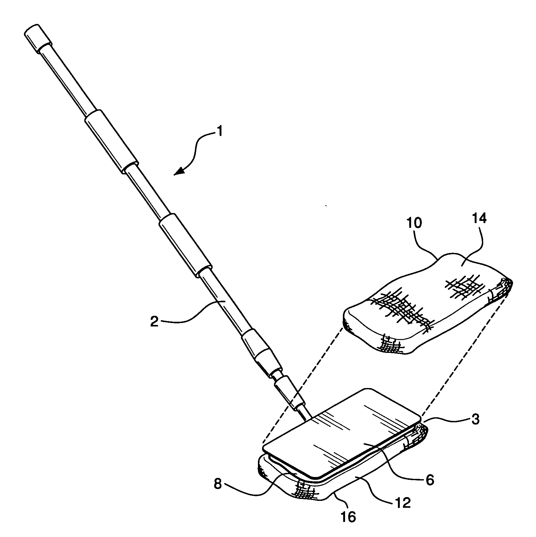
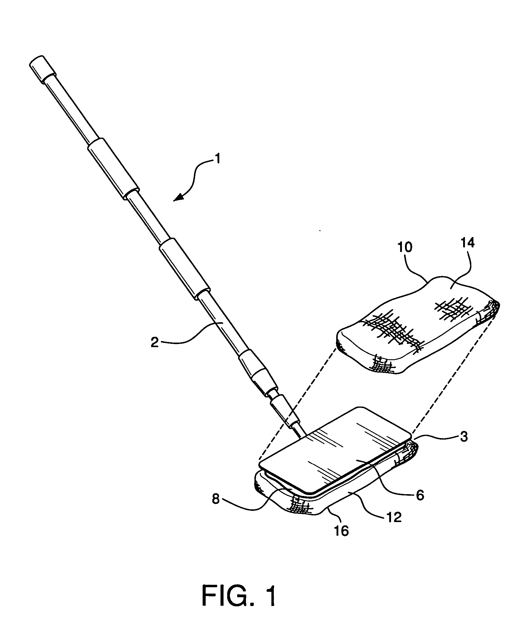
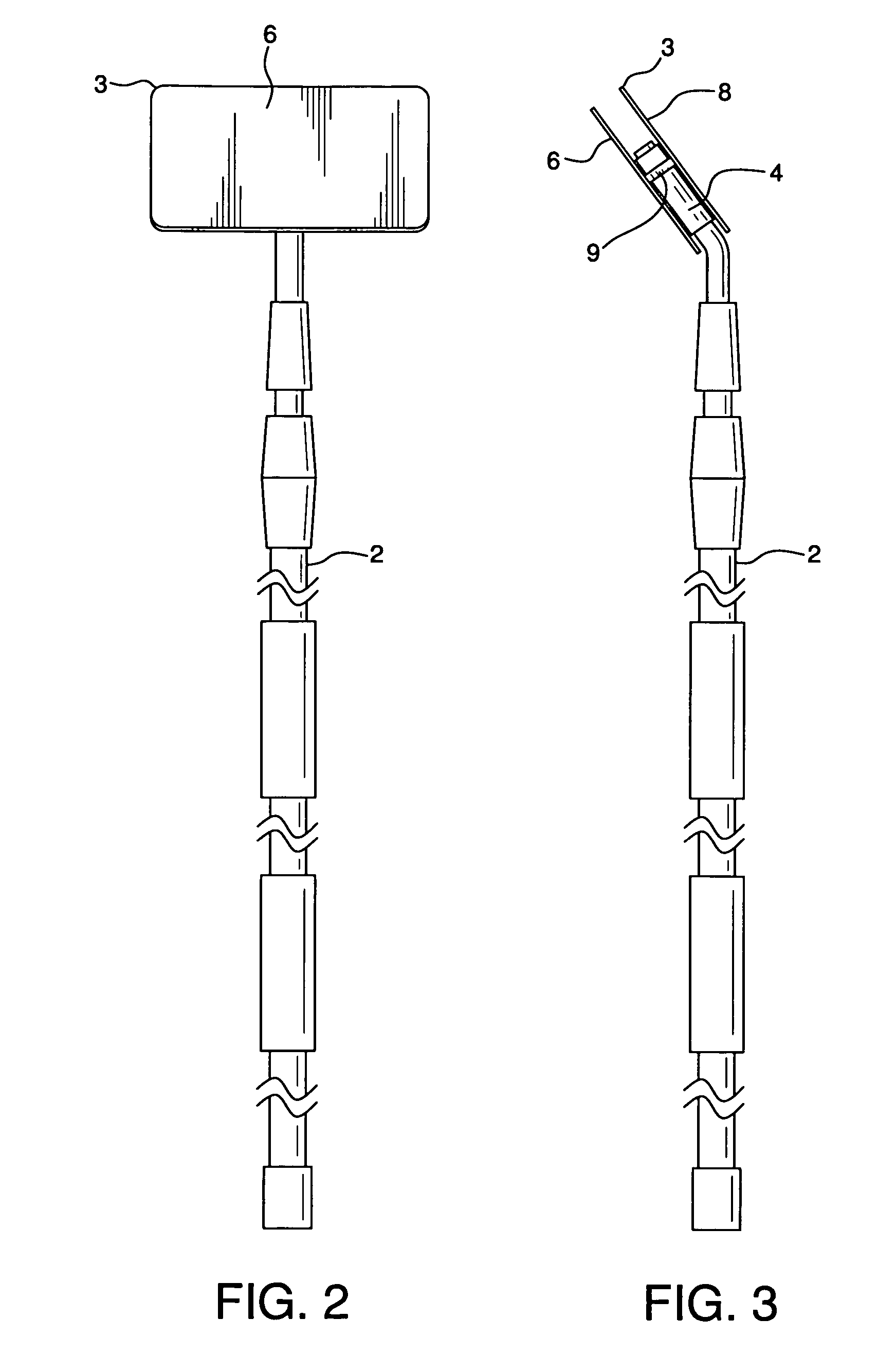
[0012] Cleaning implement 1 comprises handle 2 connected to mop head 3 by universal swivel joint 4. Joint 4 permits 360° rotational movement of cleaning head 3 in relation to handle 2. Such a universal swivel joint is known in the art and is commonly used for cleaning not only horizontal, but vertical and angled surfaces.

[0013] Handle 2 can be a unitary member or it can be telescoping in nature to permit its length to be longitudinally adjustable for various uses, including for cleaning high or wide surfaces. Such handles are often used in combination with automobile brush type cleaners, where extension of a handle is helpful in reaching surfaces where access may be difficult.

[0014] Cleaning head 3 comprises dual supports shown in FIGS. 1-3 as being parallel aligned plate members 6 and 8, interconnected such as by intermediate support 9. Plate members 6 and 8 are configured to receive separate cleaning elements 10 and 12 respectively. Although not so restricted, cleaning elements ...


PUM

PropertyMeasurementUnit
cleaning surfacesaaaaaaaaaa
rotateable movementaaaaaaaaaa
rotational movementaaaaaaaaaa

Abstract

A cleaning tool implement has a cleaning head having dual parallel aligned supports. The supports can take the form of interconnected parallel plates which are configured and sized to receive and removeably secure cleaning elements, for example, bonnets with stranded mop, scrub pad, brush, cloth and sponge surfaces, which can be adapted for removable attachment to the plates. The handle of the cleaning tool is connected to the cleaning head via a universal swivel joint which permits the head to rotate 360° in relation to the handle. This rotational movement permits the cleaning tool to be used on an infinite number of vertical, horizontal, angled, raised, and low surfaces.

Description

BACKGROUND OF THE INVENTION [0001] There are many handled cleaning tools which employ a variety of cleaning heads for various cleaning functions. The cleaning head on most common cleaning implements comprises a handle connected to a single cleaning element, e.g. a strand mop element, scrubber component, spongemop head, etc. These cleaning implements offer satisfactory cleaning, but since they each only have one cleaning element, their versatility is limited. As a result, the use to which the implement is put is restricted to the sole function of the cleaning elements and so the implement itself has limited application. SUMMARY OF THE INVENTION [0002] It is thus the object of the present invention to provide a cleaning implement which overcomes the limitations and disadvantages of prior cleaning implements. [0003] It is an object of the present invention to the provide a cleaning implement which allows the use of two different cleaning elements, thus providing versatility for the imp...

Claims


Application Information

Patent Timeline
Patent Type & Authority Applications(United States)
IPC IPC(8): A47L13/12
CPCA47L13/12
Inventor PETNER, ROBERT E.
Owner QUICKIE MFG
Learn More