Heat storing device

a heat storage device and heat storing technology, which is applied in indirect heat exchangers, lighting and heating apparatuses, laminated elements, etc., can solve the problems of increased manufacturing cost, increased manufacturing cost, and difficulty in turbulent fluid flu, so as to facilitate connection, simplify the structure of connection, and simplify the effect of heat storage devi

Inactive Publication Date: 2006-09-07
HONDA MOTOR CO LTD
View PDF3 Cites 43 Cited by
  • Summary
  • Abstract
  • Description
  • Claims
  • Application Information

AI Technical Summary

Benefits of technology

[0028] Desirably, each of the plates comprises a quadrilateral plate having a multiplicity of the fluid passages formed by substantially straight channels extending between two mutually opposite sides of the four sides of the quadric-lateral. In this case, mutually intersecting fluid passages of the stacked plates can be easily made to connect at the positions where they intersect. The structure for making them connect can be made simpler.
[0029] In a preferred form, the heat storing device further includes one fluid inlet header fronting onto two adjacent sides of the quadrilateral and one fluid outlet header fronting onto the other two sides of the stack of the quadrilateral plates, the fluid inlet header communicating with one end of each fluid passage and the fluid outlet header communicating with the other end of each fluid passage. In this case, one fluid inlet header can be connected to one end of all of the mutually intersecting fluid passages. From the one fluid inlet header, fluid can be distributed to this one end of all of the mutually intersecting fluid passages. One fluid outlet header can be connected to the other end of all of the mutually intersecting fluid passages. Fluid can be collected from the other end of all of the mutually intersecting fluid passages and guided out by one fluid outlet header. Accordingly, only one each of the member for guiding fluid into the multiple fluid passages from outside and the member for guiding the fluid from the fluid passages to outside are needed, the number of parts is low and the heat storing device can be made simple.
[0030] Preferably, a blocking plate is further provided between the fluid inlet header and the multiple plates and between the fluid outlet header and the multiple plates for blocking off the ends of the heat storing material spaces from the ends of the fluid passages. In this case, by the simple construction of just providing blocking plates, the ends of the heat storing material spaces and the ends of the fluid passages adjacent to these heat storing material spaces can be blocked off from each other easily with the blocking plates.
[0031] Desirably, the positions where the multiple fluid passages intersect are arrayed with a fixed pitch. In this case, eddy currents can be created at intervals of the fixed pitch in the fluid flowing through the flow passages. And because eddy currents are created in many locations, the efficiency of heat exchange between the heat storing material and the fluid can be increased further.
[0032] Preferably, the second plate is designed to assume the same shape as the first plate when turned upside-down with respect to the first plate and changed in phase through 90° with respect to the first plate. In this case, the first plate and the second plate can be used commonly. Therefore, because only one type of plate is needed, the manufacturing cost can be lowered.

Problems solved by technology

However, because the fluid Flu is just made to strike small semi-spherical spacers 203 projecting from the surfaces of the heat storing plates 202, it is not easy for the fluid Flu to be made turbulent.
However, because the heat transfer fins 311 to 313 are provided, the manufacturing cost increases.
However, with a heat exchanger 400 like this, because many thinly sliced heat transfer fins 403 are provided on upper and lower heat transfer plates 401, 401, the manufacturing cost increases.
Furthermore, because a fluid is made to pass between large heat transfer fins 403, compared to the degree of the improvement in heat exchange efficiency, the degree of the increase in fluid pressure loss is extremely large.

Method used


Image

  • Heat storing device
  • Heat storing device
  • Heat storing device

Examples


Embodiment Construction

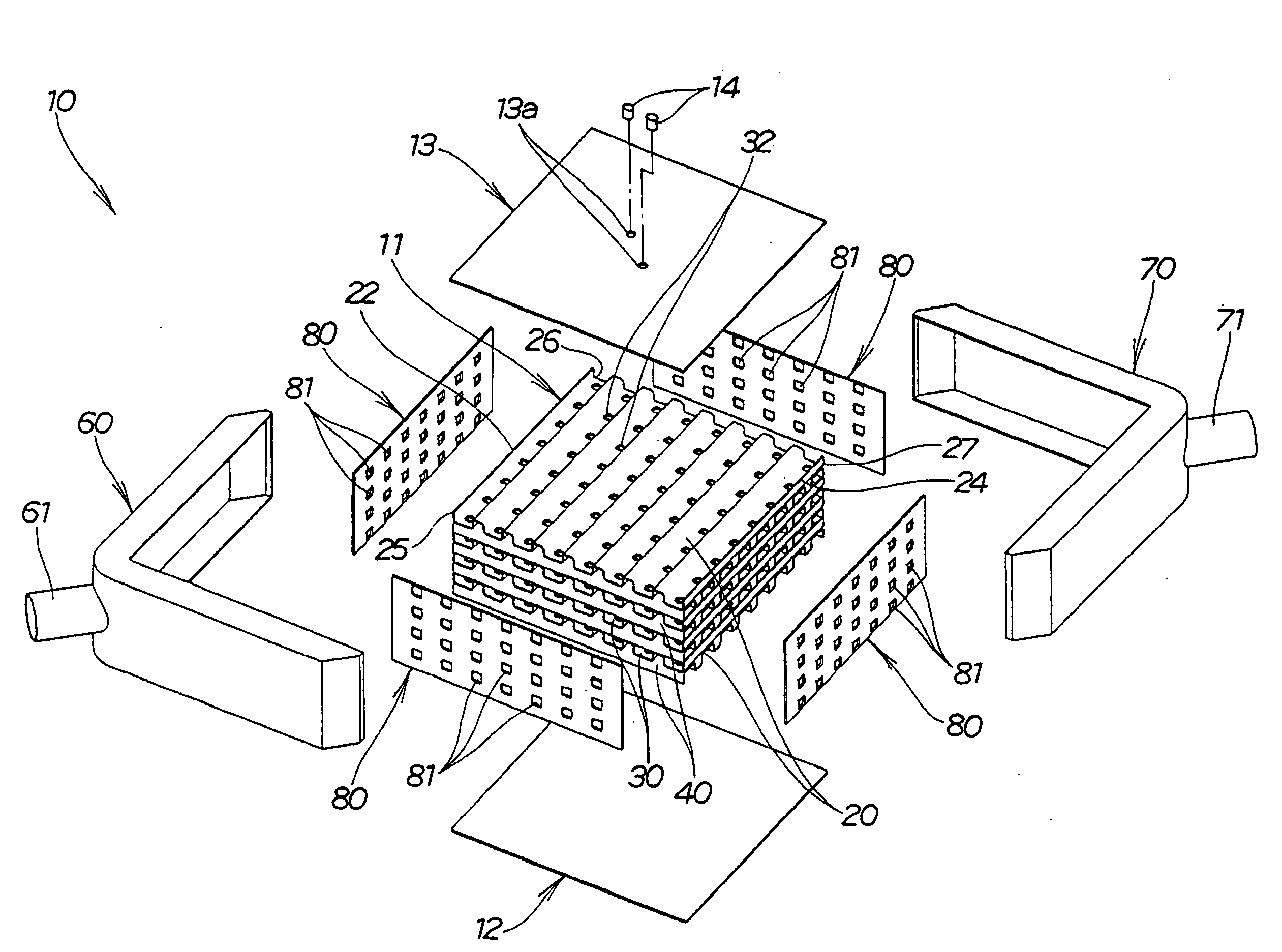
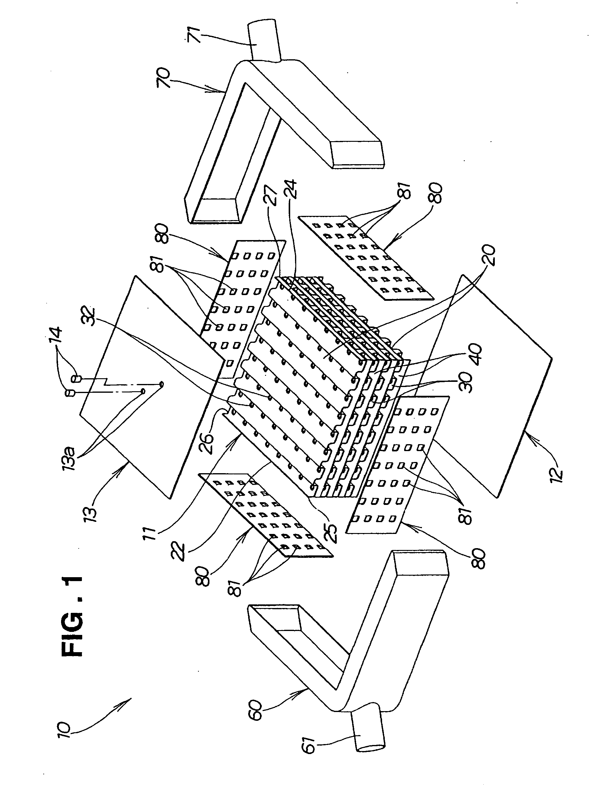
[0061] FIGS. 1 to 10 illustrate a heat storing device according to a first preferred embodiment of the present invention.

[0062] As shown in FIG. 1, the heat storing device 10 of this first preferred embodiment is made up of a heat storing module 11, a bottom plate 12 for covering a lower face of the heat storing module 11, a top plate 13 for covering an upper face of the heat storing module 11, a fluid inlet header 60 and a fluid outlet header 70 for covering side faces of the heat storing module 11, and four blocking plates 80 interposed between the side faces of the heat storing module 11 and the headers 60 and 70.

[0063] First the heat storing module 11 will be described, and after that the other members 12, 13 and 60 to 80 will be described.

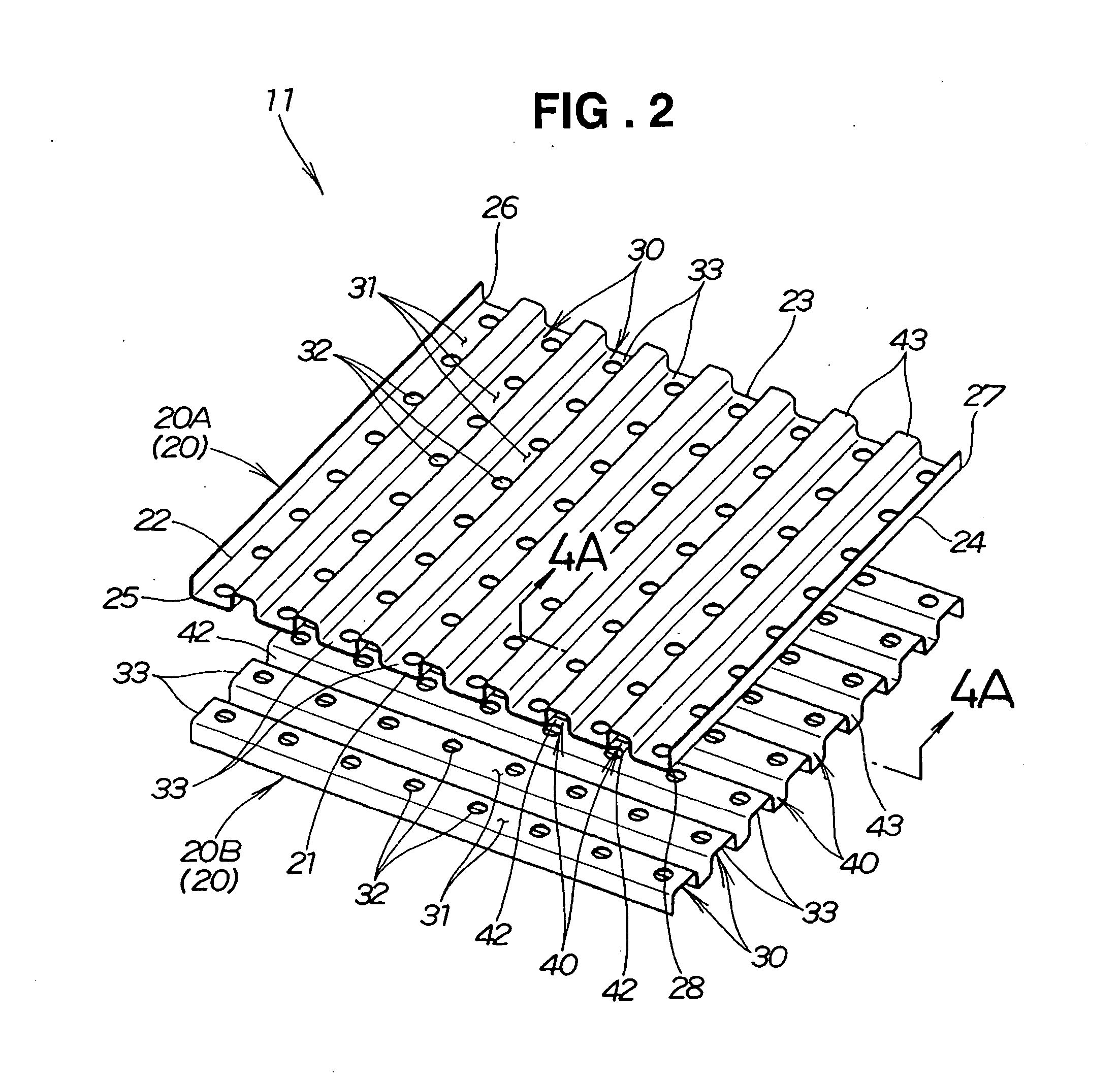
[0064] The heat storing module 11 is made up of multiple flat plates 20 in a stack and integrally has multiple heat storing material spaces 30 and multiple fluid passages 40. The plates 20 will be described below.

[0065] As shown in FIG. 2 ...


PUM


Abstract

A heat storing device for exchanging heat energy between a heat storing material and a fluid. The heat storing device has a heat storing module having heat storing material spaces filled with a heat storing material and fluid passages for a fluid to flow through adjacent to the heat storing material spaces. The heat storing module includes multiple plates in a stack. Each of the multiple plates has fluid passages in one side thereof. In mutually adjacent pairs of plates, the sides having the fluid passages face each other. When each pair of plates is seen face-on, with respect to the fluid passages of one of the plates, the fluid passages of the other plate intersect substantially at right angles, and the fluid passages of the two plates connect at these positions where they intersect.

Description

FIELD OF THE INVENTION [0001] This invention relates to a heat storing device for exchanging heat energy between a heat storing material and a heat exchange fluid. BACKGROUND OF THE INVENTION [0002] In recent years, the development of heat storing devices designed to achieve effective use of energy by transferring heat energy stored in a heat storing material to a heat exchange fluid such as cooling water has been being pursued. For example in an engine, whereas a lot of waste heat is produced while the engine is running, if heat is transferred to the engine at the time of starting, starting becomes smooth. By employing a heat storing device, it is possible to store waste heat while the engine is running and use it to warm up the engine at the time of starting. Various technologies for raising the heat exchange efficiency of this kind of heat storing device are known, as shown in JP-A-2004-271119 and JP-A-2003-336979. [0003] Various technologies for raising the heat exchange efficie...

Claims


Application Information

Patent Timeline
Patent Type & Authority Applications(United States)
IPC IPC(8): F28D19/00
CPCF28D20/02Y02E60/145Y02E60/14Y10S165/902
Inventor KUDO, TOMOHIDE
Owner HONDA MOTOR CO LTD
Why Eureka
Try Eureka