Modular lighting system

a module and lighting technology, applied in lighting and heating apparatus, lighting support devices, light source combinations, etc., can solve the problems of increasing the cost of leds, and limiting the use of leds to single-bulb us

Inactive Publication Date: 2006-09-07
OLSEN JEREMY E
View PDF15 Cites 156 Cited by
  • Summary
  • Abstract
  • Description
  • Claims
  • Application Information

AI Technical Summary

Benefits of technology

[0012] It has been recognized that it would be advantageous to develop an LED lighting system that allows flexible independent control of a plurality of LEDs having a variety of functional states.
[0013] It has also been recognized that it would be advantageous to develop an LED lighting system that is flexible and easily reconfigurable.

Problems solved by technology

Until recently, the use of LEDs has tended to be limited to single-bulb use in relatively low light applications, such as miniature train sets, instrument panels, electronics, pen lights and, more recently, outdoor decorative lights such as Christmas lights.
First, they are long-lasting.
While LEDs are still significantly more expensive than incandescent or fluorescent light devices of comparable illumination, their cost is continually coming down.
This factor diminishes the flexibility of LEDs in many instances.
For example, while RGB LEDs are available, their use in the same manner as conventional Christmas lights generally will not allow exercise of their entire functionality, at least not in any flexible way.
Moreover, even where LEDs are substituted for incandescent or other bulbs, typical lighting systems are generally inflexible, and do not allow significant reconfiguration.

Method used


Image

  • Modular lighting system
  • Modular lighting system
  • Modular lighting system

Examples


Embodiment Construction

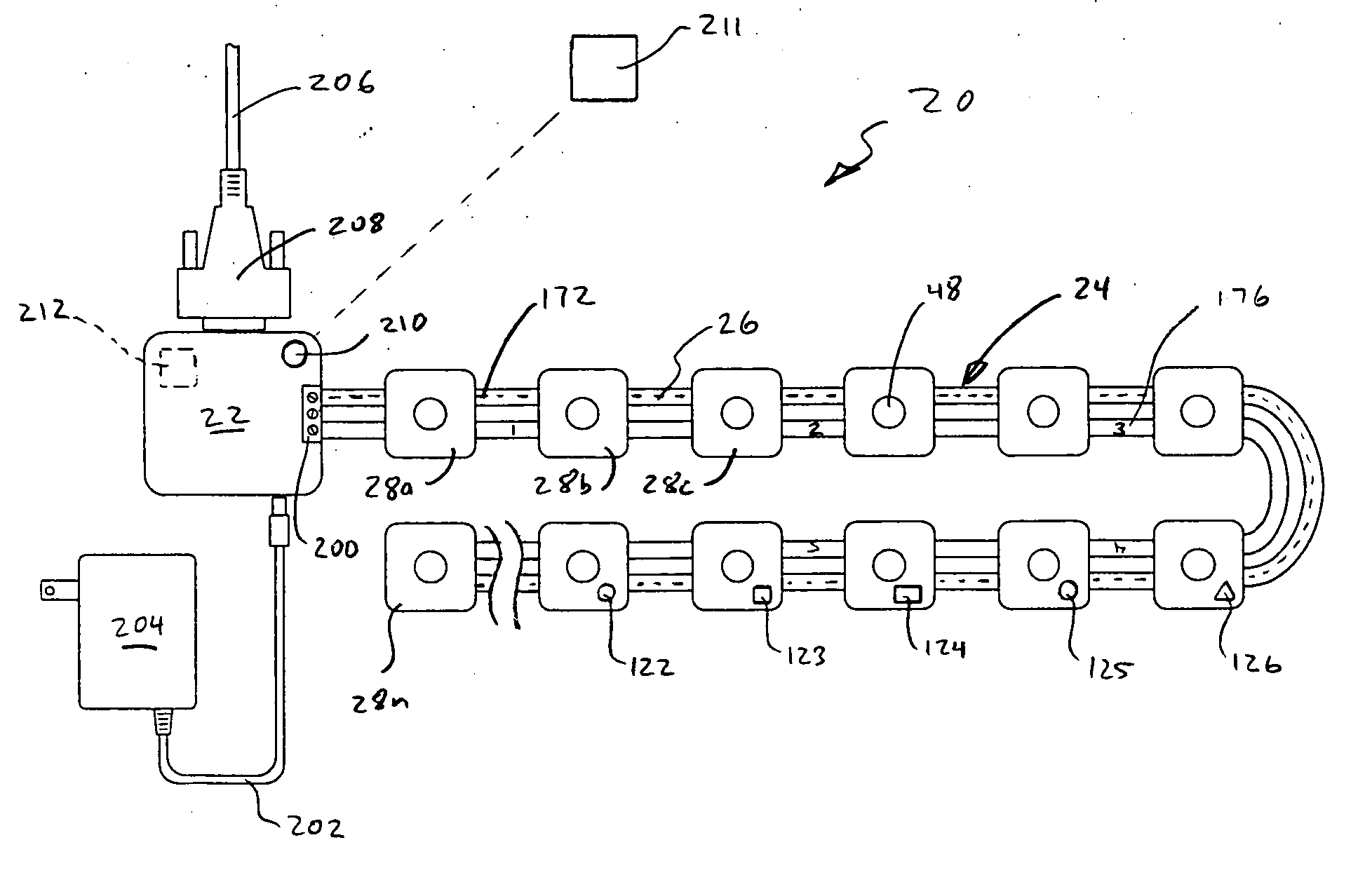
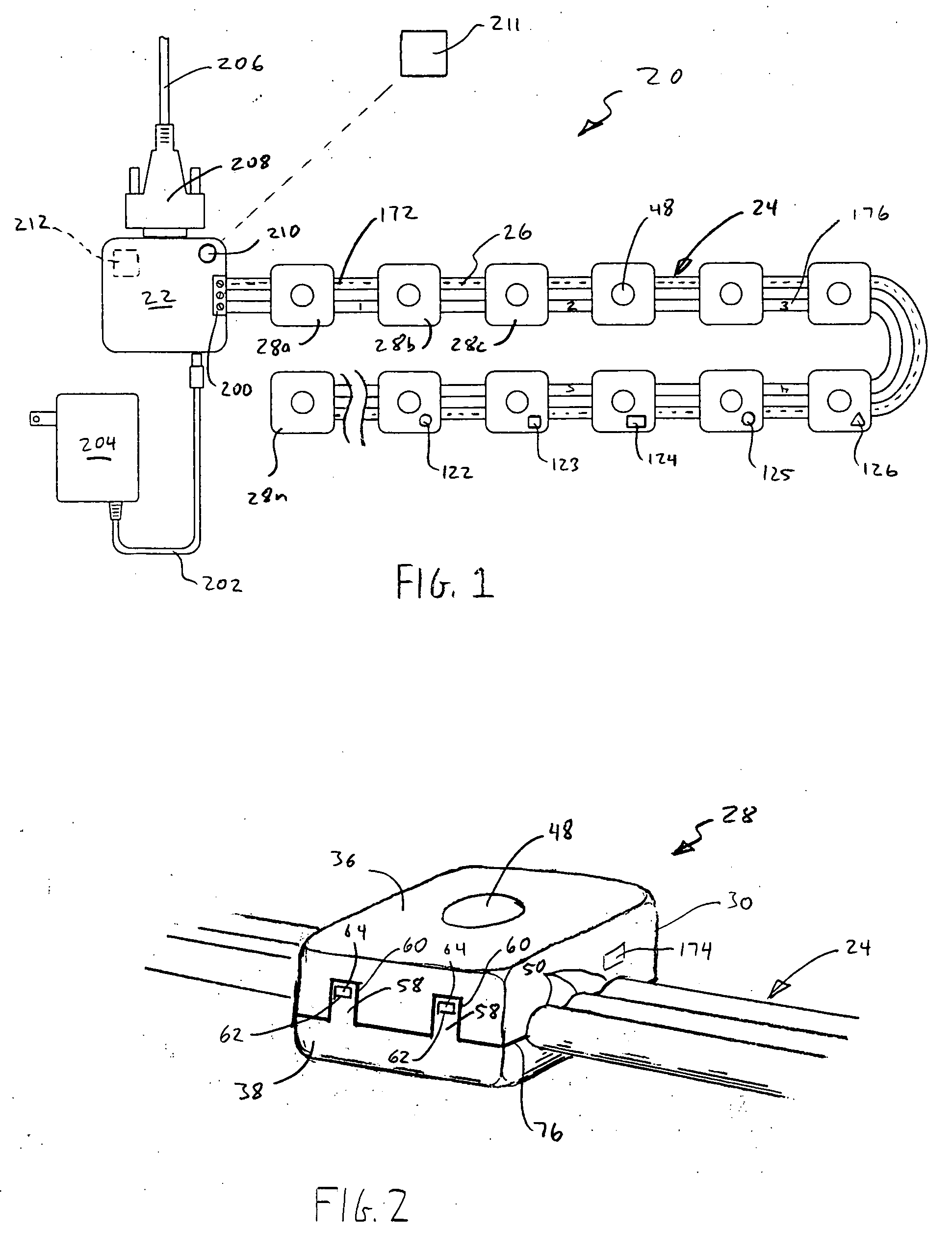
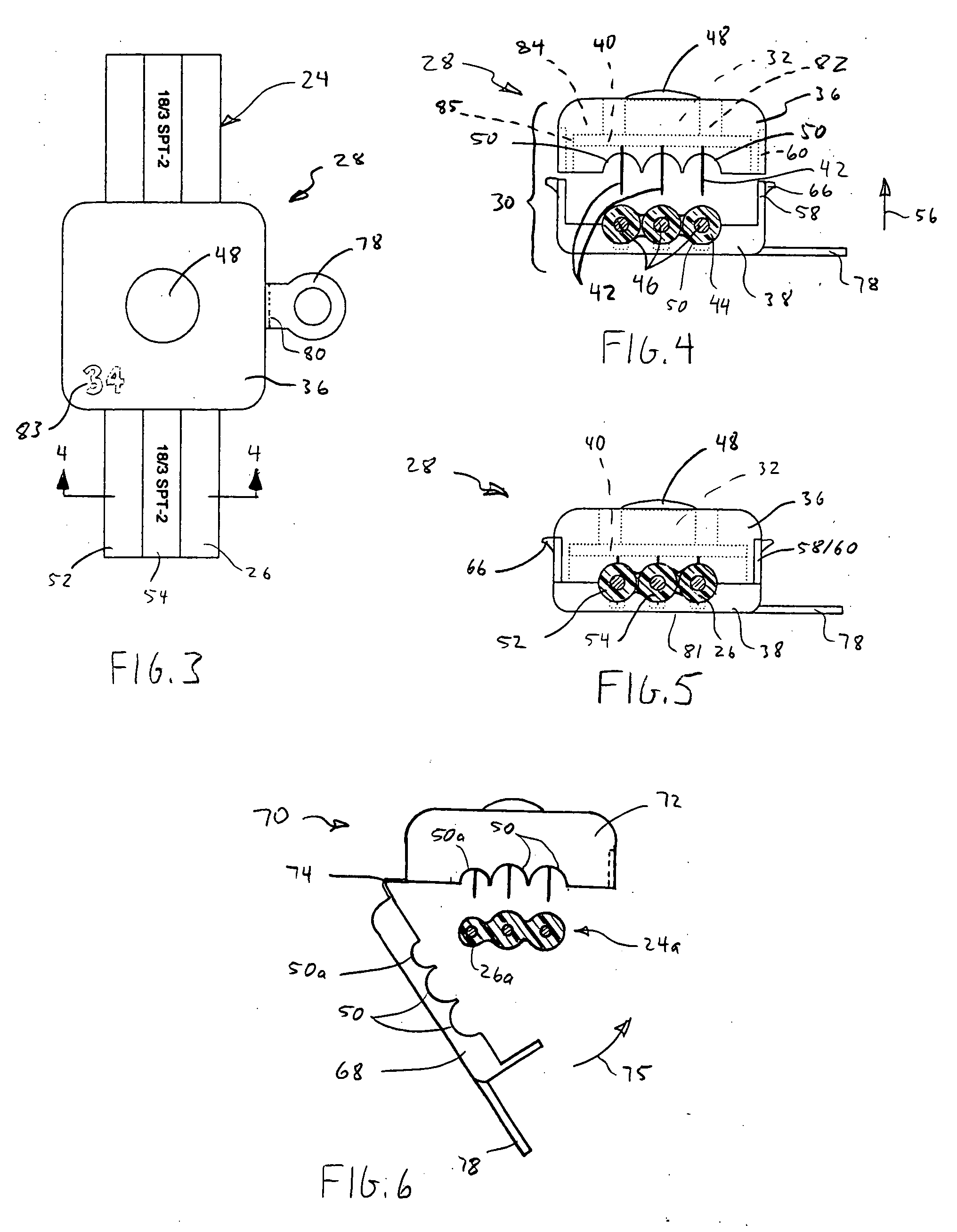
[0035] One embodiment of a modular lighting system in accordance with the invention is shown in FIG. 1. The lighting system 20 comprises a microprocessor interface 22, a multi-conductor (e.g. 3 conductors) wire 24, including a data line 26, and a plurality of modular LED nodes 28a-n disposed along the wire. As shown in FIGS. 2-5, each node comprises a modular housing 30 that is selectively attachable to and removable from the multi-conductor wire at any desired location. Each housing contains an LED or LED array 32 that is mounted upon a circuit board (40 in FIG. 4), which also supports a dedicated microprocessor chip (34 in FIG. 7B) and related circuitry.

[0036] As used herein, the terms “LED” and “LED array” are used interchangeably to refer to the actual light emitting diode 32 (or array of light emitting diodes) associated with a single node. The term “node” is used to refer to the entire lighting unit, i.e. the housing 30 and everything contained in it, including the LED, the c...


PUM


Abstract

A modular lighting system includes a multiple conductor wire, including a common data wire, and a plurality of nodes, disposed along the multiple conductor wire. Each node includes an LED and a node microprocessor, having a unique address. The node microprocessor is configured to independently control illumination of the LED according to node-specific operating instructions that are transmitted via the common data wire.

Description

BACKGROUND [0001] 1. Field of the Invention [0002] The present invention relates generally to LED lighting systems. More particularly, the present invention relates to a modular system for providing and controlling a plurality of LED lights along a common conductor wire. [0003] 2. Related Art [0004] Light-emitting diodes (LEDs) are becoming increasingly popular as replacements for incandescent bulbs and other lighting devices in a variety of applications. Until recently, the use of LEDs has tended to be limited to single-bulb use in relatively low light applications, such as miniature train sets, instrument panels, electronics, pen lights and, more recently, outdoor decorative lights such as Christmas lights. However, more recent developments have broadened their utility and applicability. This wider use of LEDs is readily visible in traffic lights, automobile tail lights and head lights, and other common applications. Also, because of their low power consumption and high light outp...

Claims


Application Information

Patent Timeline
Patent Type & Authority Applications(United States)
IPC IPC(8): H05B39/00H05B45/50
CPCF21V21/002F21V31/005F21Y2101/02F21Y2113/007H05B33/0821H05B33/0842H05B37/0254F21Y2115/10F21Y2113/17H05B45/20H05B45/40H05B45/50H05B47/22H05B47/18H05B47/19
Inventor OLSEN, JEREMY E.
Owner OLSEN JEREMY E
Why Eureka
Try Eureka