
Method of generating optimised stack code

a stack code and optimization technology, applied in the direction of program code transformation, program control, instruments, etc., can solve the problems of comparatively little research on stack-based optimization, the method does not work with a directed acyclic graph or directed graph, and the awkwardness of directly optimizing stack cod

Inactive Publication Date: 2006-09-07
INNAWORKS DEV
View PDF55 Cites 22 Cited by
  • Summary
  • Abstract
  • Description
  • Claims
  • Application Information

AI Technical Summary

Benefits of technology

[0036] Preferably, if rule (c) applies then the traversal of the graph is rolled-back to a position where the result of a node can be stored according to a predetermined rule. 13. The rolling-back may include un-collapsing one or more collapsed nodes.
[0037] It is preferred that a collapse pattern which creates a single collapsed node is associated with a code generation rule which leaves the result of the si

Problems solved by technology

“Optimising stack code directly is awkward for multiple reasons .
Second, the expressions are not explicit, and must be located on the stack.
Comparatively little research in optimisation had been done for stack-based representations.
However this method does not work with a directed acyclic graph or directed graph.
However the stack allocation method does not reorder other instructions.
These dependences hamper a wide range of program optimisations in the presence of PEIs, such as instruction scheduling, instruction selection (across a PEI), loop transformations, and parallelization.
This impedes the performance of programs written in languages like Java, in which PEIs are quite common.
In addition, previous approaches to optimisation of instruction scheduling do not take account of the performance or size of the generated stack-code where common sub-expressions are involved.
Koopman's approach and its derivatives are only partial solutions, as they cannot fully overcome sub-optimal instruction sequences generated by an instruction scheduler that is not taking account of the cost and performance of the generated stack-code.
However by working only on the stack code, without a dependence graph, it is difficult to determine which code reordering is safe, consequently limiting the extent of optimisation.

Method used


Image

  • Method of generating optimised stack code
  • Method of generating optimised stack code
  • Method of generating optimised stack code

Examples


Embodiment Construction

[0067] The present invention will be described in relation to a method of generating optimised stack code for a stack-based machine from a register-based representation of the code.

[0068] It will be appreciated that the method may be implemented within optimisers or compilers.

[0069] The advantage of the method of the present invention is the production of compact and efficient code for stack based machines from a register based representation.

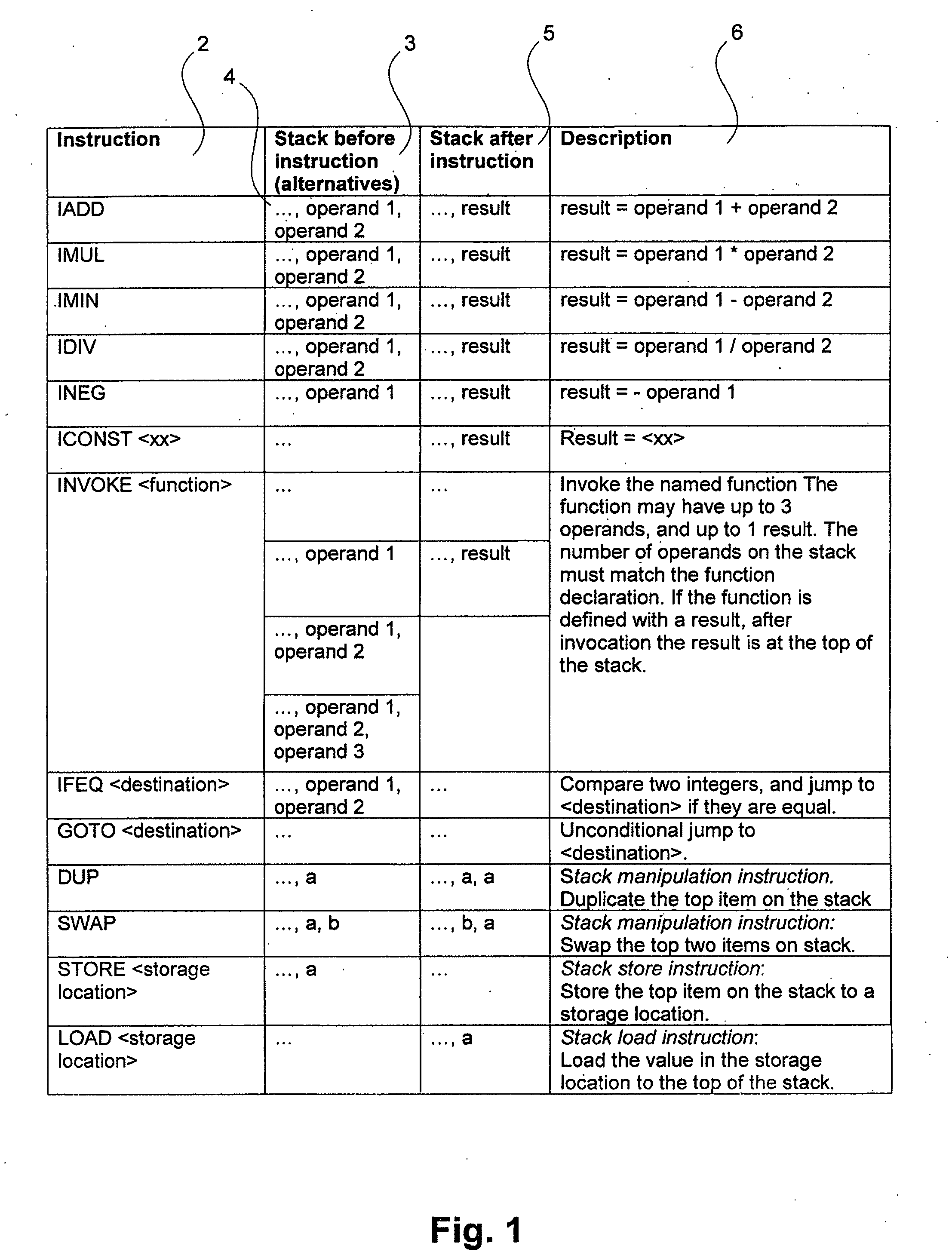
[0070] The method will decide for each expression whether the result of that expression is required to be stored in the general store area, and what stack manipulation instructions, stack store instructions and stack load instructions are required to be inserted.

[0071] The method of the invention makes efficient use of the characteristics of a stack-based machine and the particular set of stack manipulation instructions available on a particular stack-based machine, by generating code with “minimal” number of stack store instructions, stack...


PUM


Abstract

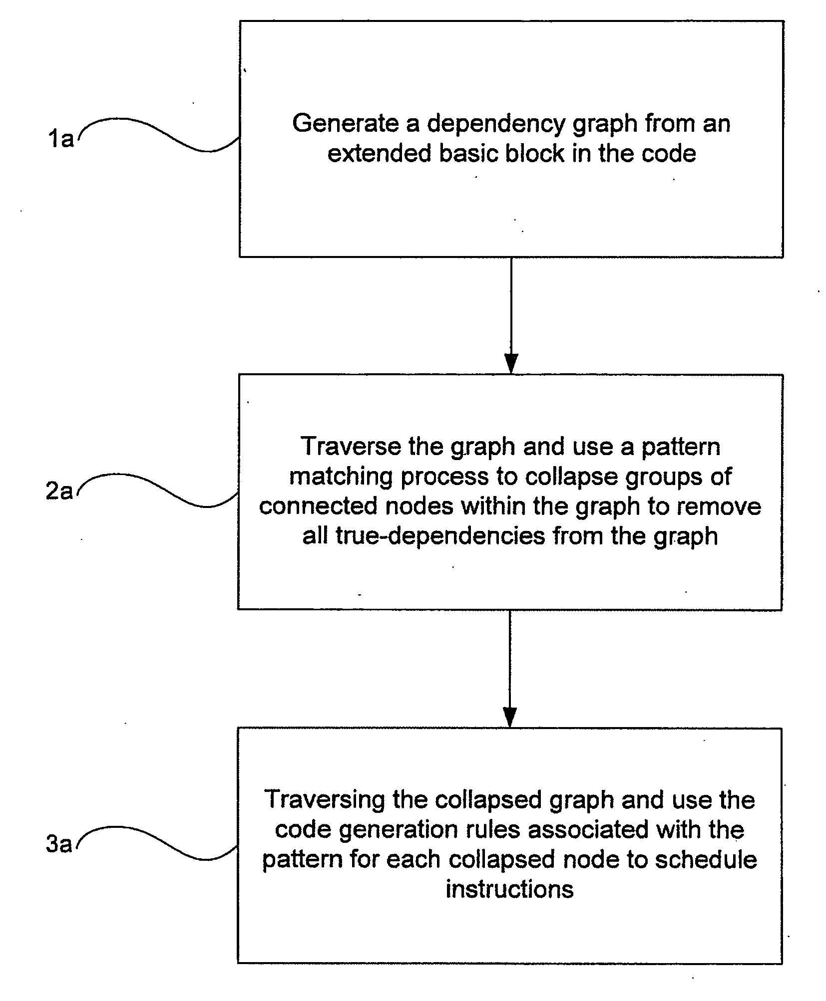
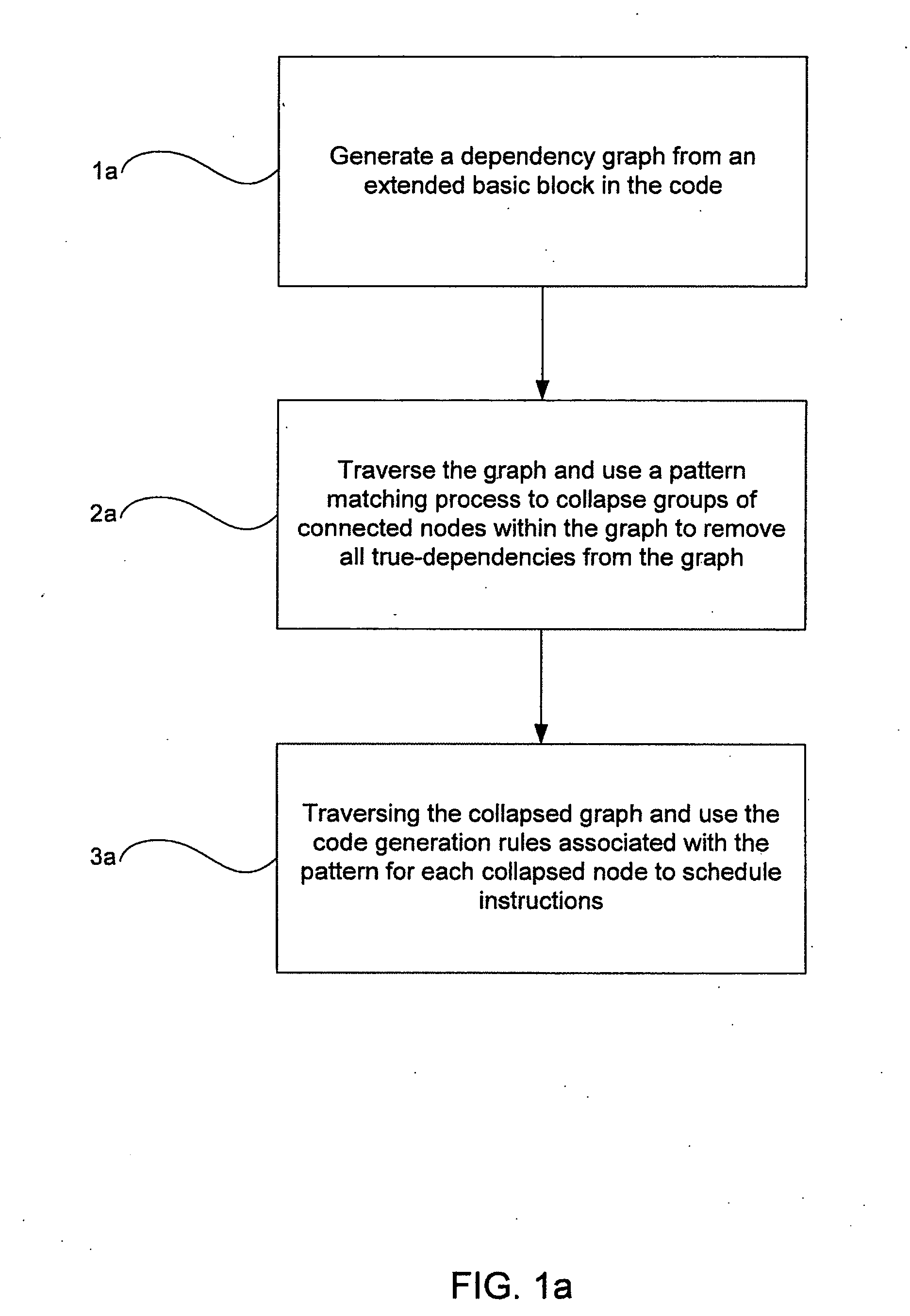
The present invention relates to a method for generating optimised stack code for a stack-based machine from a register-based representation of the original code. The method includes the steps of: creating a dependence graph from the representation; removing true dependencies from the dependence graph by matching portions of the dependence graph with a set of patterns; and defining stack code corresponding to the dependence graph using code generation rules associated with each pattern.

Description

FIELD OF INVENTION [0001] The present invention relates to a method of generating optimised stack code. More particularly, but not exclusively, the present invention relates to generating optimised stack code for a stack-based machine from a register-based representation of the original code by converting the original code into a dependence graph and collapsing the dependence graph to remove true dependencies. BACKGROUND TO THE INVENTION [0002] The stack model of execution uses a stack to hold temporary results during evaluation of a program. Implementations of the stack model, such as Java virtual machines for execution of stack-based Java bytecode, access the stack more efficiently than local variables. Thus, converting local variable accesses into stack accesses can improve the performance of stack-based programs. [0003] A stack-based machine (a machine implementing the stack-based model of execution) is characterised by an instruction set including instructions popping one or mo...

Claims


Application Information

Patent Timeline
IPC IPC(8): G06F9/45
CPCG06F8/41
Inventor CHENG, STEPHEN M.K.
Owner INNAWORKS DEV
Learn More