Composite containment case for turbine engines

a technology for turbine engines and containment cases, which is applied in the direction of machines/engines, liquid fuel engines, braids, etc., can solve the problems of foreign objects being ingested into the engine, affecting the performance of the engine, and a portion of the impacted blade being torn loose from the rotor,

Active Publication Date: 2006-09-14
GENERAL ELECTRIC CO
View PDF6 Cites 61 Cited by
  • Summary
  • Abstract
  • Description
  • Claims
  • Application Information

AI Technical Summary

Benefits of technology

[0007] In one aspect, a composite fan casing for a gas turbine engine is provided. The casing includes a core having a plurality of core layers of reinforcing fiber bonded together with a thermosetting polymeric resin. Each core layer includes a plurality of braided reinforcing fiber tows. The braids of reinforcing fiber tows are aligned in a circumferential direction with each fiber tow including a plurality of reinforcing fibers. The core also includes at least one additional fiber tow braided into at least one predetermined axial location to form at least one concentrated stiffening ring.
[...

Problems solved by technology

When engines operate in various conditions, foreign objects may be ingested into the engine.
The foreign objects may impact a blade resulting in a portion of the impacted blade being torn loose from a rotor.
Such a condition, known as foreign object damage, may cause the rotor blade to pierce an engine casing resulting in cracks along an exterior surface of the engine casing, and possible injury to nearby personnel.
Additionally, the foreign object damage may ...

Method used


Image

  • Composite containment case for turbine engines
  • Composite containment case for turbine engines
  • Composite containment case for turbine engines

Examples


Embodiment Construction

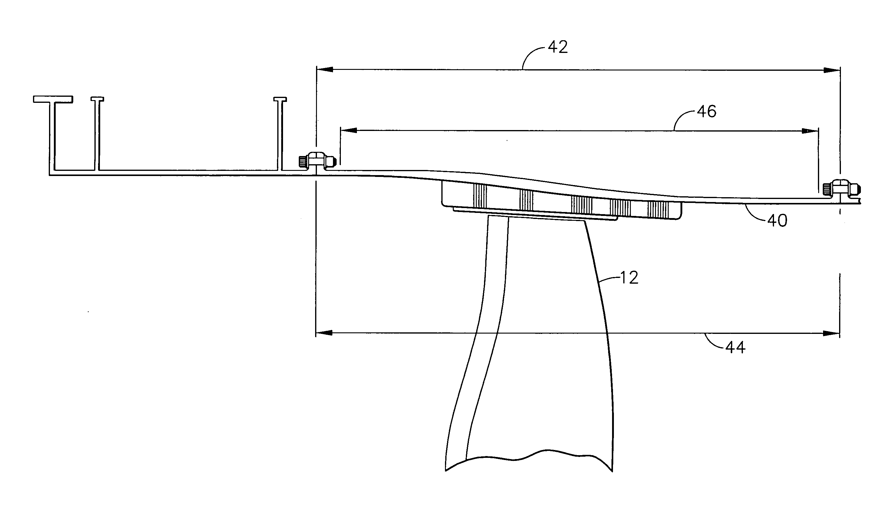
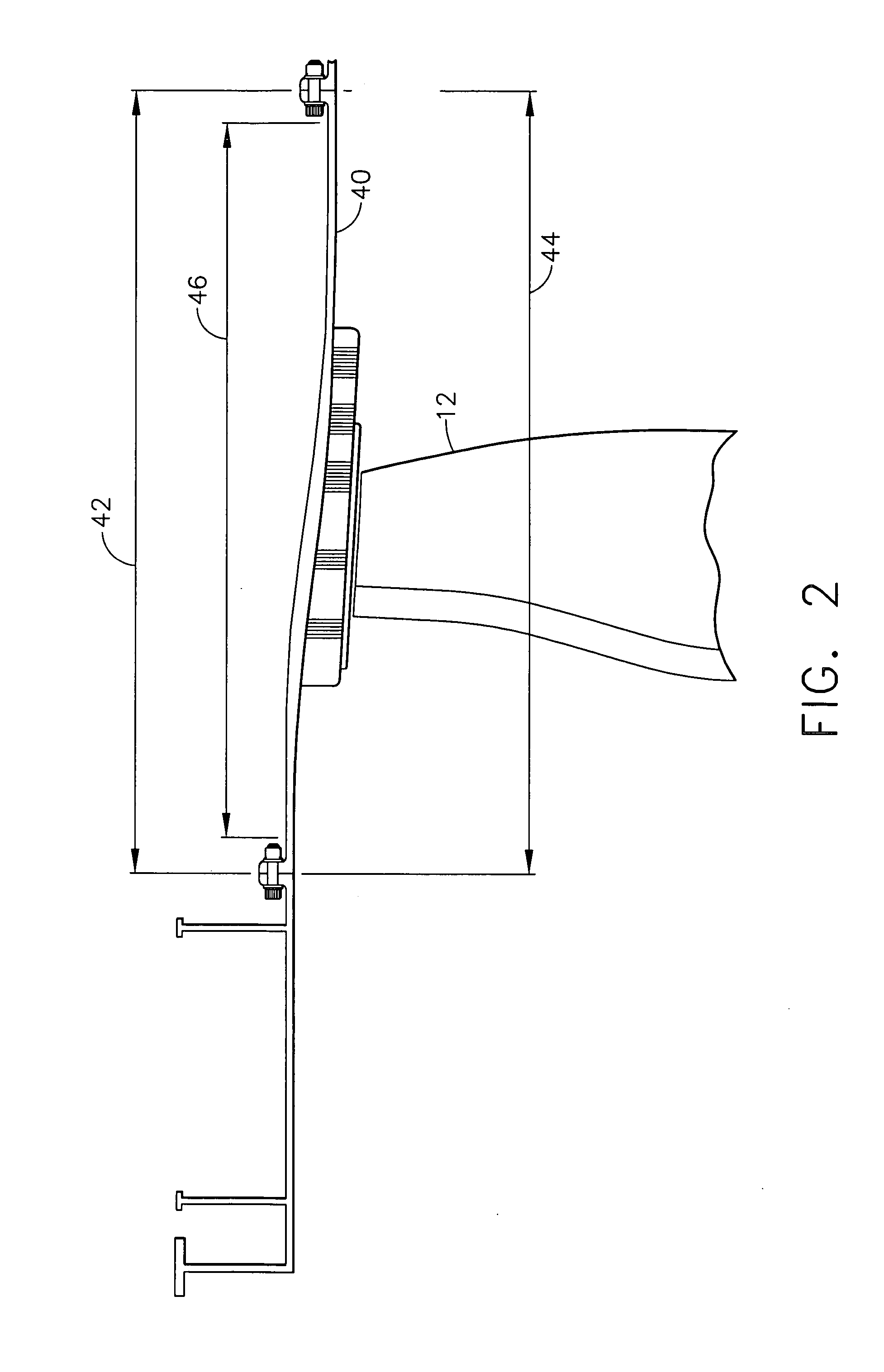
[0014] A composite fan casing for a gas turbine engine is described below in detail. The casing includes a core having a plurality of core layers of reinforcing fiber bonded together with a thermosetting polymeric resin. Each core layer includes a plurality of braided reinforcing fibers with the braids of reinforcing fibers aligned in a circumferential direction. The composite casing resists crack propagation under impact loading.

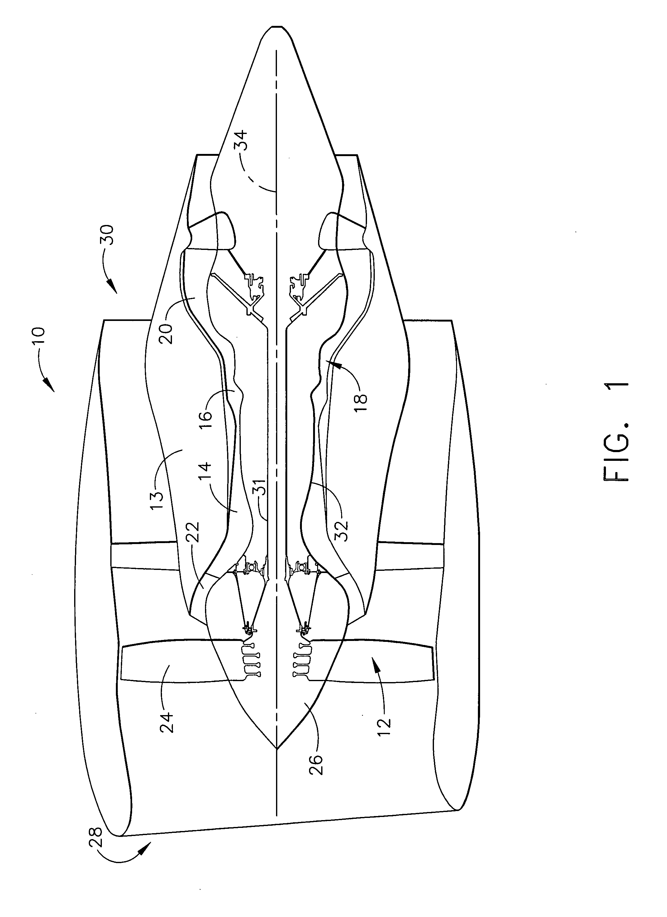
[0015] Referring to the drawings, FIG. 1 is a schematic illustration of a gas turbine engine 10 that includes a fan assembly 12 and a core engine 13 including a high pressure compressor 14, and a combustor 16. Engine 10 also includes a high pressure turbine 18, a low pressure turbine 20, and a booster 22. Fan assembly 12 includes an array of fan blades 24 extending radially outward from a rotor disc 26. Engine 10 has an intake side 28 and an exhaust side 30. In one embodiment, the gas turbine engine is a GE90 available from General Electric Company, Cincin...


PUM


Abstract

A composite fan casing for a gas turbine engine includes, in an exemplary embodiment, a core having a plurality of core layers of reinforcing fiber bonded together with a thermosetting polymeric resin. Each core layer includes a plurality of braided reinforcing fiber tows. The braids of reinforcing fiber tows are aligned in a circumferential direction with each fiber tow including a plurality of reinforcing fibers. The core also includes at least one additional fiber tow braided into at least one predetermined axial location to form at least one concentrated stiffening ring.

Description

CROSS REFERENCE TO RELATED APPLICATIONS [0001] This application is a continuation-in-part of U.S. patent application Ser. No. 11 / 020,483, filed Dec. 23, 2004.BACKGROUND OF THE INVENTION [0002] This invention relates generally to gas turbine engines, and more particularly, to methods and apparatus for operating gas turbine engines. [0003] Gas turbine engines typically include high and low pressure compressors, a combustor, and at least one turbine. The compressors compress air which is mixed with fuel and channeled to the combustor. The mixture is then ignited for generating hot combustion gases, and the combustion gases are channeled to the turbine which extracts energy from the combustion gases for powering the compressor, as well as producing useful work to propel an aircraft in flight or to power a load, such as an electrical generator. [0004] When engines operate in various conditions, foreign objects may be ingested into the engine. More specifically, various types of foreign o...

Claims


Application Information

Patent Timeline
IPC IPC(8): F02K3/04
CPCF01D21/045F01D25/24Y02T50/672D04C1/02D10B2505/02F05D2300/702F05D2300/44F05D2300/603Y02T50/60
Inventor XIE, MINGMITCHELL, STEPHEN C.LACHAPELLE, DONALD G.BRALEY, MICHAEL SCOTTROBERTS, GARY D.HOPKINS, DALE
Owner GENERAL ELECTRIC CO
Why Eureka
Try Eureka