

Sensor-incorporated tire and tire condition estimating method
a technology of sensor-incorporated tires and tire condition estimation, which is applied in vehicle tyre testing, instruments, roads, etc., can solve the problems of inability to accurately measure lateral force and extremely difficult to detect lateral force with a small gain, etc., and achieve accurate detection of lateral force generated in tires, accurate estimation, and measurement more accurate
- Summary
- Abstract
- Description
- Claims
- Application Information
AI Technical Summary
Benefits of technology
Problems solved by technology
Method used
Image

Examples
embodiment 1
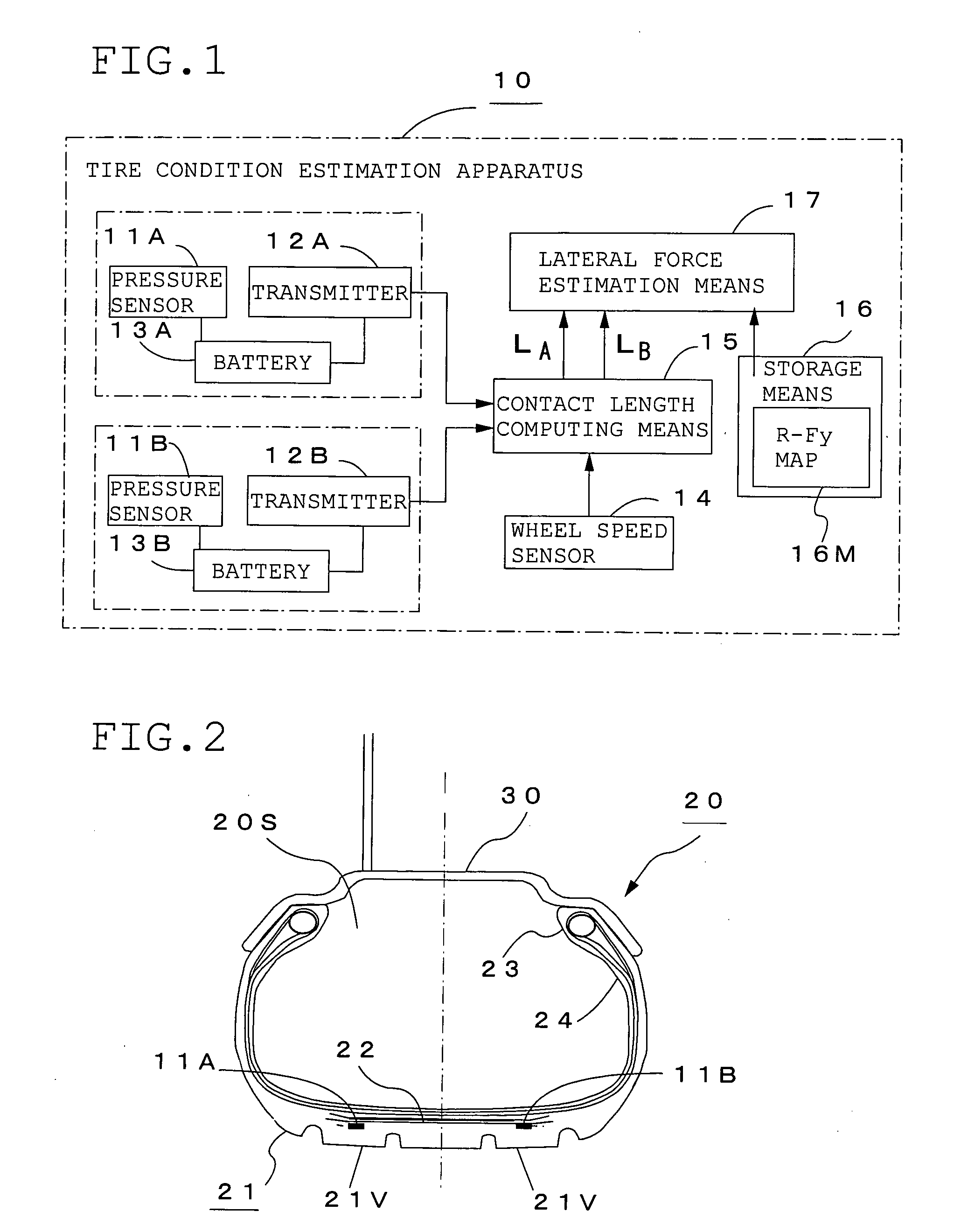
[0051]FIG. 1 is a functional block diagram showing the constitution of a tire condition estimation apparatus 10 according to Embodiment 1, and FIG. 2 is a diagram of a sensor-incorporating tire 20 according to the present invention. This tire condition estimation apparatus 10 comprises pressure sensors 11A and 11B as input detection means for detecting that the predetermined position of a tire tread portion 21 contacts the road to produce an input from the road, which are buried in the sensor-incorporating tire 20, transmitters 12A and 12B for transmitting detection data from the above pressure sensors 11A and 11B, batteries 13A and 13B for supplying power to the above pressure sensors 11A and 11b and the above transmitters 12A and 12B, a wheel speed sensor 14 as wheel speed measuring means such as a gear sensor for detecting a wheel speed, contact length computing means 15 for detecting the contact lengths LA and LB of positions where the above pressure sensors 11A and 11B are buri...
embodiment 2
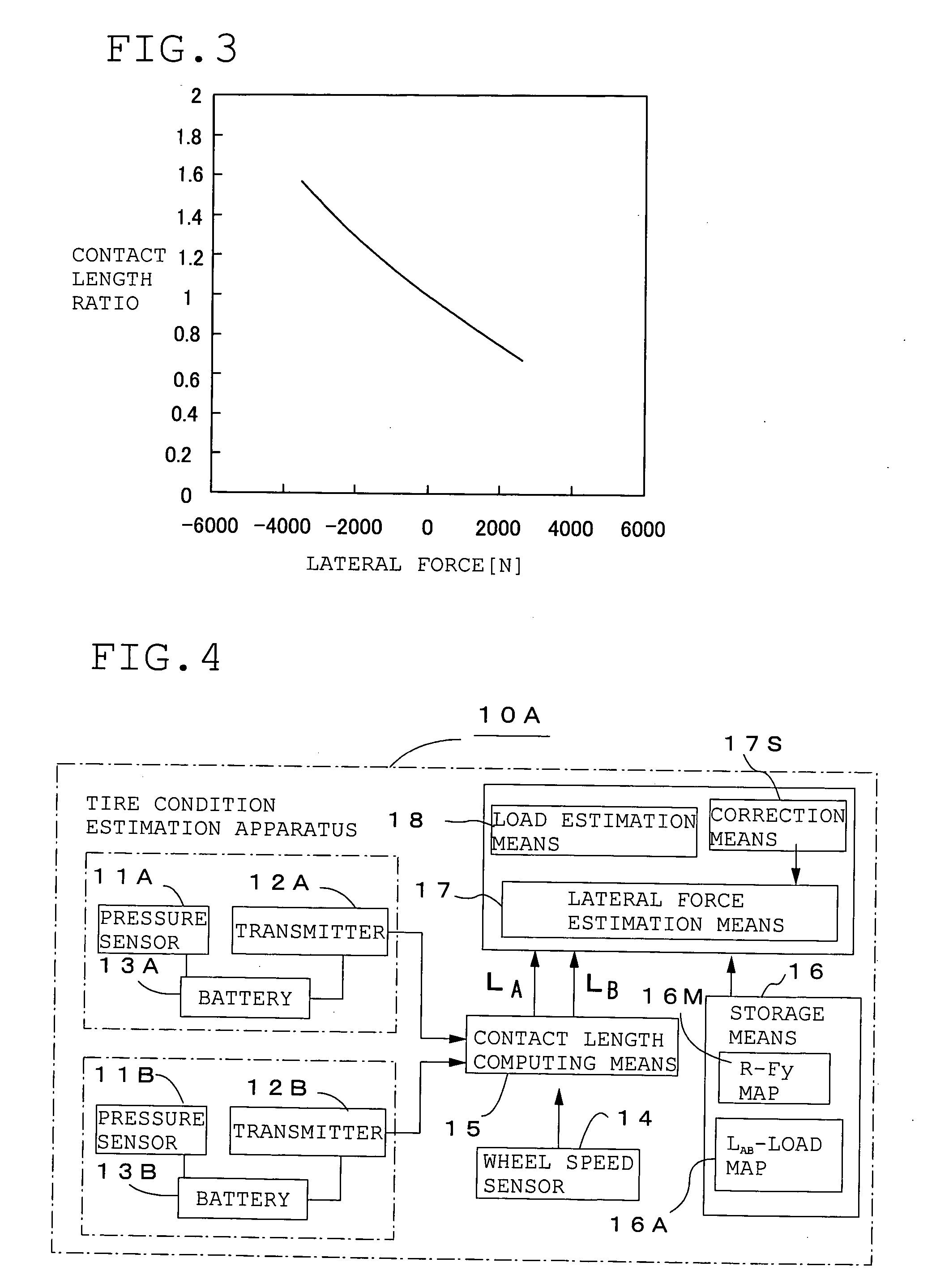
[0060] In the above Embodiment 1, the contact length ratio R=LA / LB which is the ratio of the contact length LA of the car body side to the contact length LB of the opposite side of the center in the tire axial direction of the sensor-incorporating tire 20 is computed to estimate lateral force. As shown in FIG. 4, when load estimation means 18 is provided to compute the average contact length LAB which is the average value of the above contact length LA and the contact length LB, and a load applied to the above tire 20 is estimated from this average contact length LAB, a tire condition estimation apparatus 10A which can estimate lateral force and a load can be constructed.
[0061] When lateral force is generated in the tire 20, the ground contact shape of the tire 20 becomes such as shown in FIGS. 15(A) and 15(B) that the contact length of one side of the center in the tire axial direction becomes long and that of the other side becomes short. Therefore, when a load is estimated from ...
embodiment 3
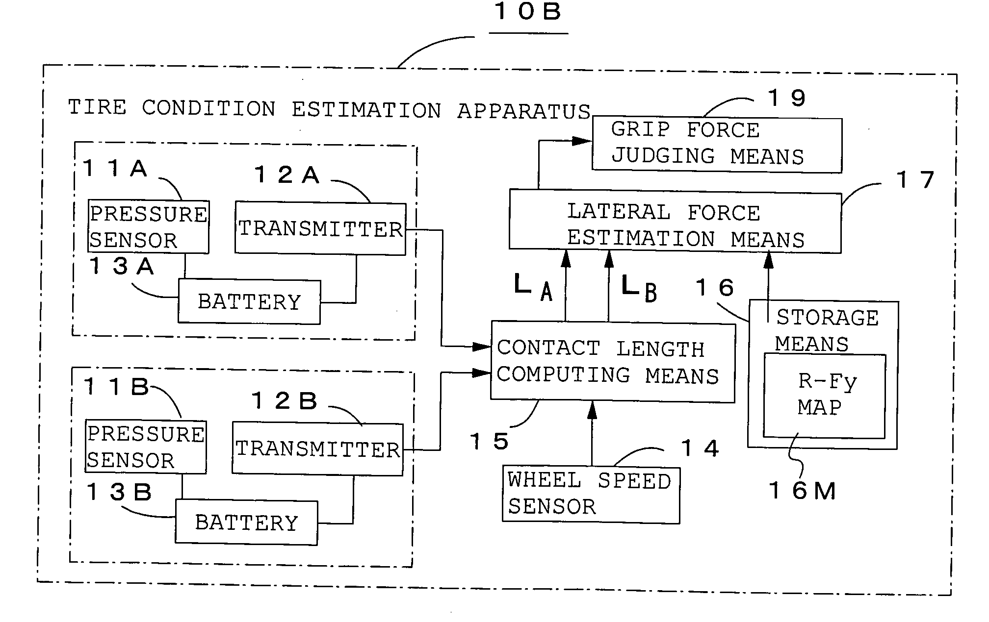
[0069] In Embodiments 1 and 2, the tire condition estimation apparatuses 10 and 10A for estimating lateral force and a load by computing the contact length ratio R=LA / LB and the average contact length LAB from the duration times of the pressure values from the pressure sensors 11A and 11B and the wheel speed from the wheel speed sensor 14 have been described. As shown in FIG. 10, grip force judging means 19 is provided in the above tire condition estimation apparatus 10 to estimate whether the tire is approaching the grip limit from a change in the contact length ratio R=LA / LB computed by the lateral force estimation means 17.
[0070] Judging that lateral force is approaching its maximum, that is, the tire grip limit, is useful for vehicle control or as a warning to a driver. Since the contact length ratio R=LA / LB is monitored in the present invention, the grip force judging means 19 judges that the tire is approaching the grip limit when a change in the above contact length ratio R=...
PUM
 Abstract
Description
Claims
Application Information