Pipe manufacturing installation and associated defect detection method

a technology for manufacturing installation and pipe manufacturing, applied in the direction of tubular articles, fluid tightness measurement using fluid/vacuum, coatings, etc., can solve the problems of high grain size, defects are then revealed, and the wall of pipes containing micro-perforation and/or crack types

Inactive Publication Date: 2006-09-14
THE MACHINES YVONAND
View PDF7 Cites 45 Cited by
  • Summary
  • Abstract
  • Description
  • Claims
  • Application Information

AI Technical Summary

Benefits of technology

[0013] Owing to these features, defects in the pipe are detected easily, which enables corrective measures to be taken in the installation to guarantee manufacturing quality.
[0016] According to another advantageous feature of the invention, the cooling tank comprises a portion of transparent wall, called the observation window, and the camera lens is arranged behind the observation window, outside the cooling tank. This particular arrangement facilitates the siting of the camera in the installation, particularly as regards water resistance, and it also means that pictures of sufficient quality are obtained for the electronic analysis circuit to process the images.

Problems solved by technology

It has been observed that this type of installation can produce pipes whose wall comprises micro-perforation and / or crack type defects.
It may be due particularly to the presence of dust in the extrusion station, to the too high grain size of the carbon black present in the pipe material, to dirt in the calibrating means, or to a defect during welding of the drippers.
These defects are then revealed, after the pipes have been set in place on the ground, for example in the form of an abnormally high consumption of irrigation liquid.

Method used


Image

  • Pipe manufacturing installation and associated defect detection method
  • Pipe manufacturing installation and associated defect detection method
  • Pipe manufacturing installation and associated defect detection method

Examples


Embodiment Construction

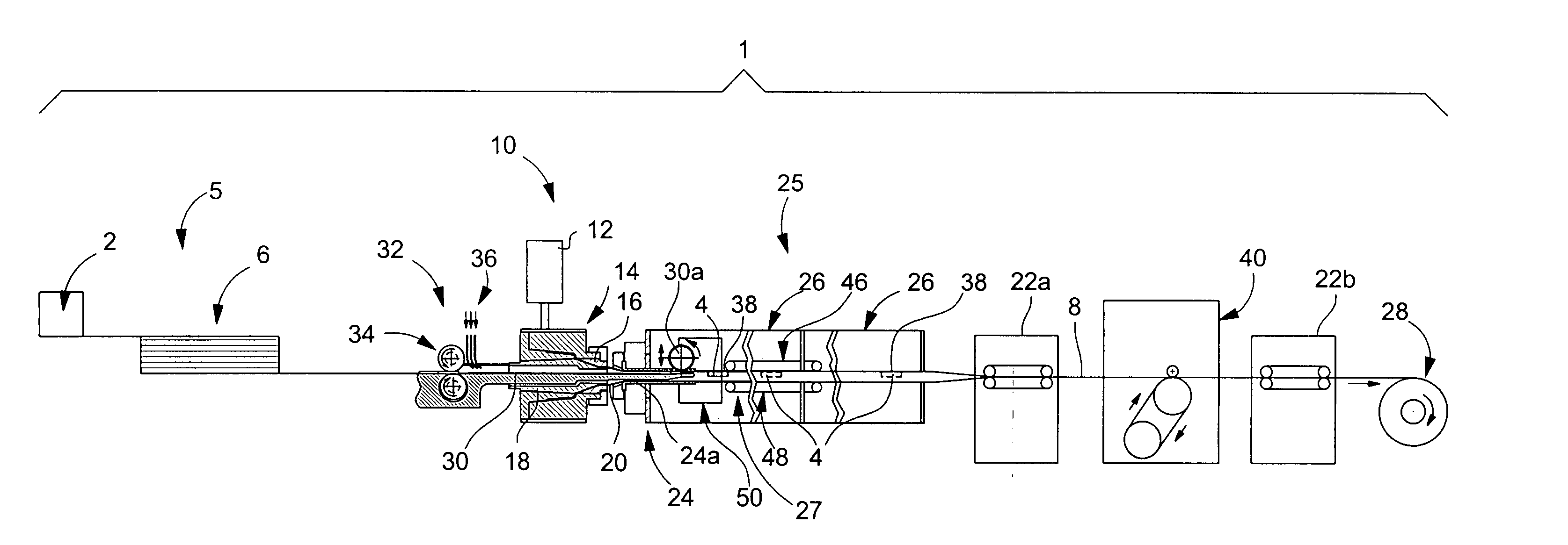
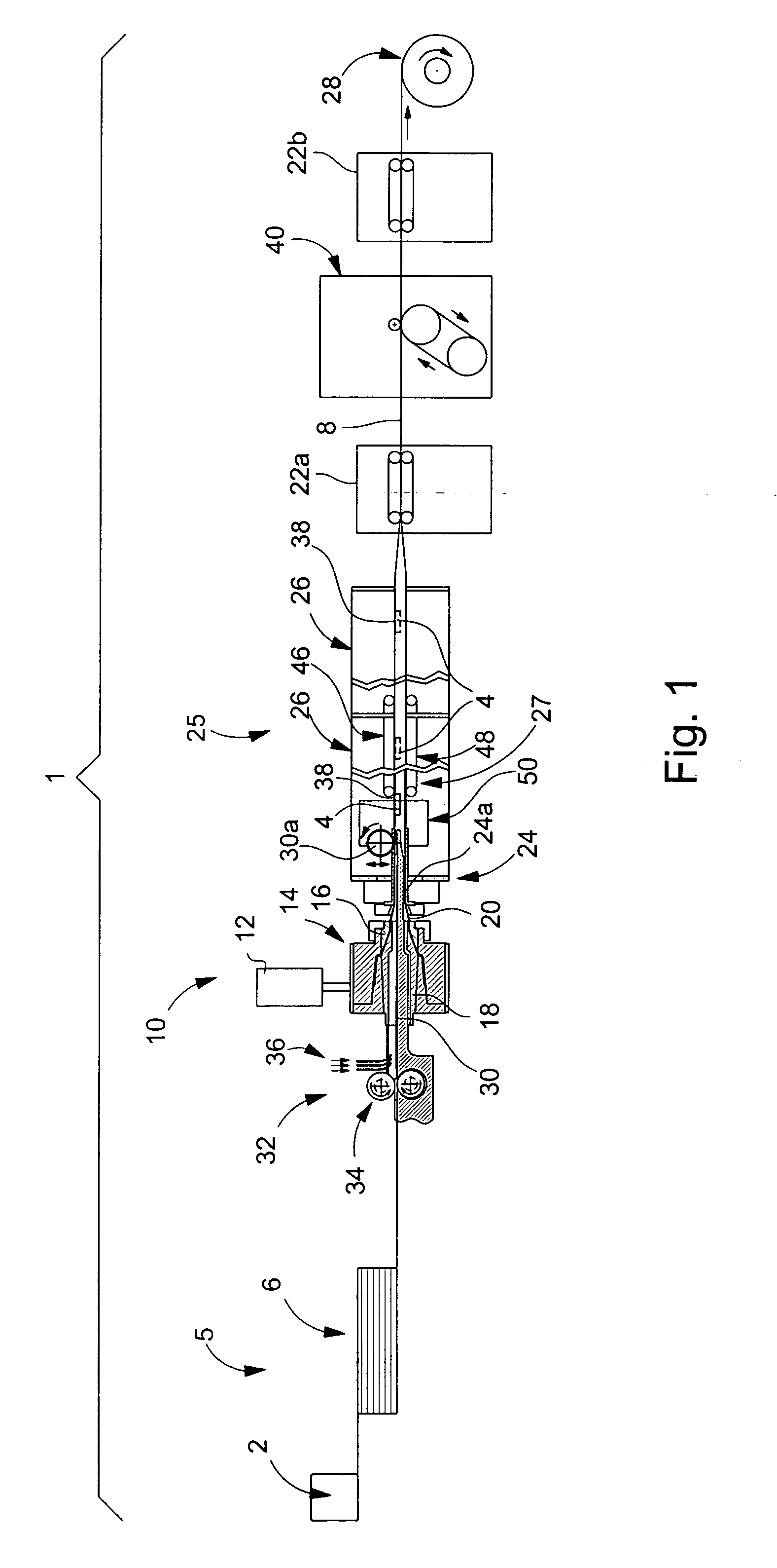
[0029]FIG. 1 is a schematic diagram of an installation for manufacturing drip type irrigation pipes. Designated as a whole by the general reference numeral 1, this installation includes in particular a feed station 5 for the drippers 4 which is followed by an extrusion station 10 for pipe 8 and a cooling station 25 for pipe 8.

[0030] Feed station 5 includes a magazine 2 such as a centrifugal bowl which sorts, orientates and positions drippers 4 in an accumulator device 6 depending upon the position that they have to have once they are inserted into irrigation pipe 8.

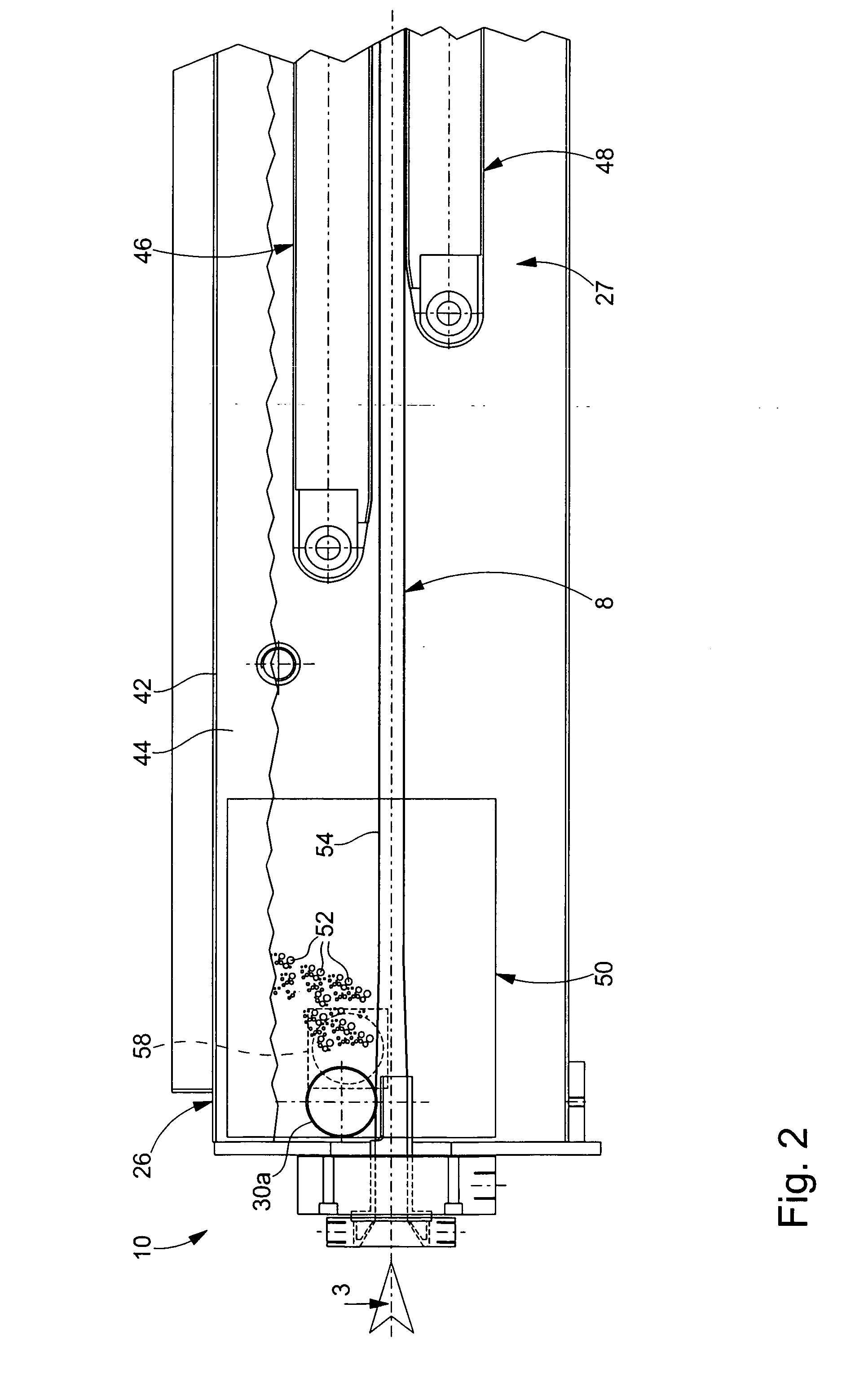
[0031] Extrusion station 10 is arranged after accumulator device 6. This extrusion station 10 includes a chamber 12 for melting the plastic material which feeds a unit 14 provided with a die 16 inside which there is provided a guide wire 18 arranged such that a tubular blank 20 comes out of die 16. Blank 20 is drawn by traction stations 22a and 22b passing through calibrating means 24 and a cooling station 25 formed by ...


PUM

PropertyMeasurementUnit
areaaaaaaaaaaa
transparentaaaaaaaaaa
stabilityaaaaaaaaaa

Abstract

The invention concerns an installation for manufacturing drip irrigation pipes comprising a dripper feed station followed by an extrusion station comprising extrusion means, means for calibrating the pipe and means for welding the drippers to the inner wall of the pipe, and followed by a cooling station for the pipe, of the type wherein the cooling station includes a cooling tank containing a cooling fluid in which the pipe is immersed, characterized in that a detection device is provided for detecting, in the cooling fluid, the emission of gas bubbles through the wall of the pipe, so as to deduce therefrom the presence of perforations and / or cracks. The invention also concerns a method for detecting perforations and / or cracks.

Description

This application claims priority from European Patent Application No. 05005241.4 filed Mar. 10, 2005, the entire disclosure of which is incorporated herein by reference. FIELD OF THE INVENTION [0001] The present invention relates to a drip irrigation pipe manufacturing installation. More specifically, the invention concerns an installation of this type comprising means for checking, in real time, the quality of the manufactured pipes. The invention concerns particularly an installation of this type comprising a cooling tank provided with a device for detecting cracks and perforations, particularly micro-perforations, in the wall of the manufactured pipe. [0002] The invention also concerns a method for detecting cracks and perforations in the wall of a hollow element. BACKGROUND OF THE INVENTION [0003] A common technique is to use, for some irrigations, so-called “drip” pipes. These are pipes whose wall is pierced, at pre-determined intervals, with holes of small diameter, through wh...

Claims


Application Information

Patent Timeline
Patent Type & Authority Applications(United States)
IPC IPC(8): B29C47/92B29C47/00B29C47/88B29C48/09B29C48/157B29C48/90B29C48/92
CPCB29C47/0023B29C47/028B29C47/882B29C47/903B29C47/92B29C2947/92295B29C2947/92304B29C2947/92428B29C2947/92933B29C2947/9298B29D23/001B29L2023/22G01M3/08B29C48/92B29C48/09B29C48/157B29C48/9115B29C48/913B29C48/919B29C48/90B29C48/903B29C48/906B29C48/908B29C2948/92295B29C2948/92304B29C2948/92428B29C2948/92933B29C2948/9298
Inventor BACH, CHRISTIANKERTSCHER, EBERHARD
Owner THE MACHINES YVONAND
Why Eureka
Try Eureka