Method and apparatus for forming a non-woven web by deposition of synthetic filaments

a synthetic filament and non-woven technology, applied in the field of non-woven webs formed by synthetic filament deposition, can solve the problems of completely unsuitable devices for drawing and depositing filaments at high speeds, and achieve the effect of special non-woven effects and limited effective distance for deflecting filament streams

Inactive Publication Date: 2006-09-14
SAURER GMBH & CO KG
View PDF3 Cites 15 Cited by
  • Summary
  • Abstract
  • Description
  • Claims
  • Application Information

AI Technical Summary

Benefits of technology

[0013] In a second method, the deflection of the filament stream is brought about by an additional air stream that flows transverse to the filaments in the advancing direction of the deposit belt. Thus it is possible to generate a deflection that acts on the filament stream in a very limited way and that additionally brings about a swirling of the filaments. The advantage of such a short distance for deflecting the filament stream is that the appearance of the flow on the outlet side of the drawing unit brought about by the filament discharge for stretching the filaments remains completely unaffected.
[0014] A markedly limited effective distance for deflecting the filament stream can also be achieved by a third method in that a shaped body is assigned to the filament stream immediately before the deposit of the filaments. The shaped body is held at a small distance above the deposit belt laterally next to the filaments. The Coanda effect is also used in order to achieve a deflection of the filament stream on the shaped body. The shaped body that dips into the boundary layer of the filament stream comprises a strong flow in the deflection direction so that the air stream remains stuck to the surface due to the physical phenomenon discovered by the physicist Coanda and thus is deflected from its guideway.
[0015] In order to achieve the impact angle that is favorable for depositing the filaments, the filaments are drawn into the guide channel preferably with a feed fluid under the effect of an excess pressure of the range

Problems solved by technology

However, the disadvantage of such methods and devices is that there exists an interrelation between the pivotable plates located opposite to one another that leads to unstable conditions in such a way that the filaments ca

Method used


Image

  • Method and apparatus for forming a non-woven web by deposition of synthetic filaments
  • Method and apparatus for forming a non-woven web by deposition of synthetic filaments
  • Method and apparatus for forming a non-woven web by deposition of synthetic filaments

Examples


Embodiment Construction

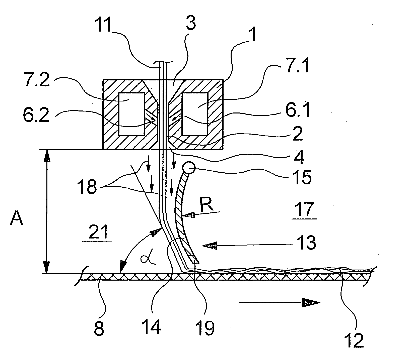
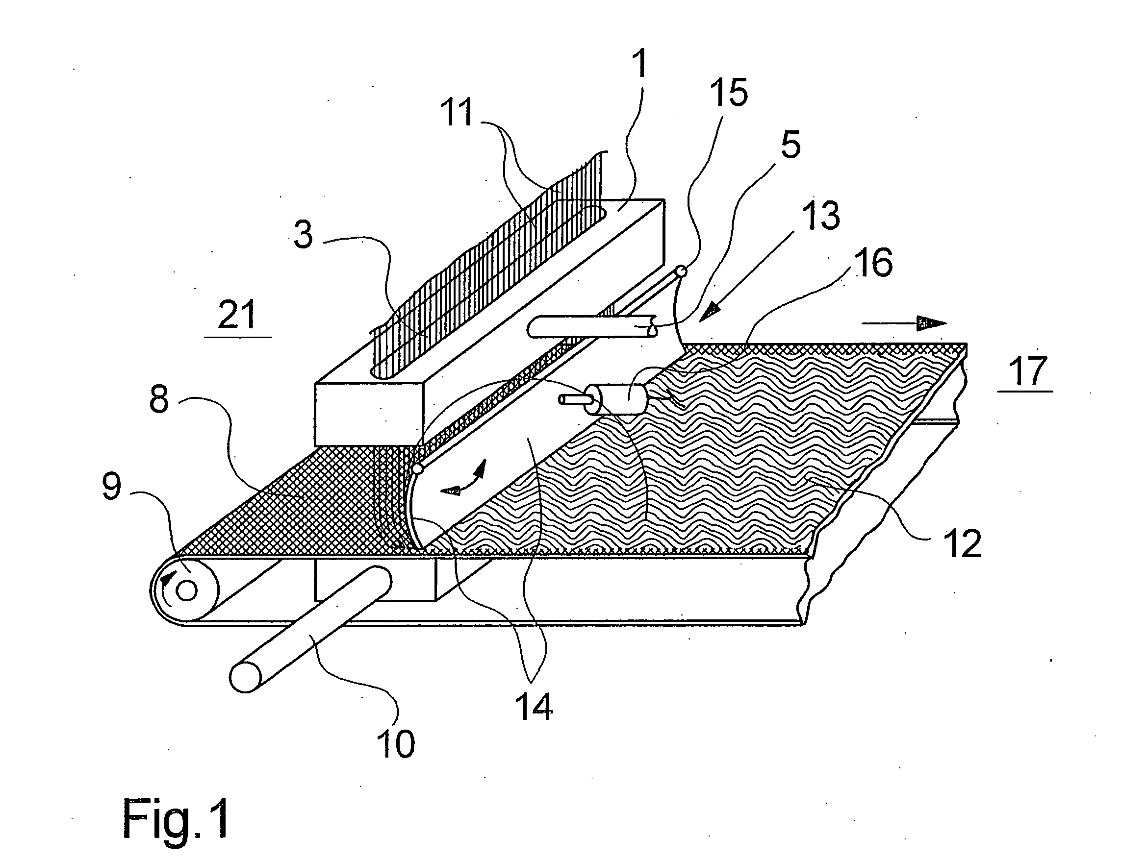
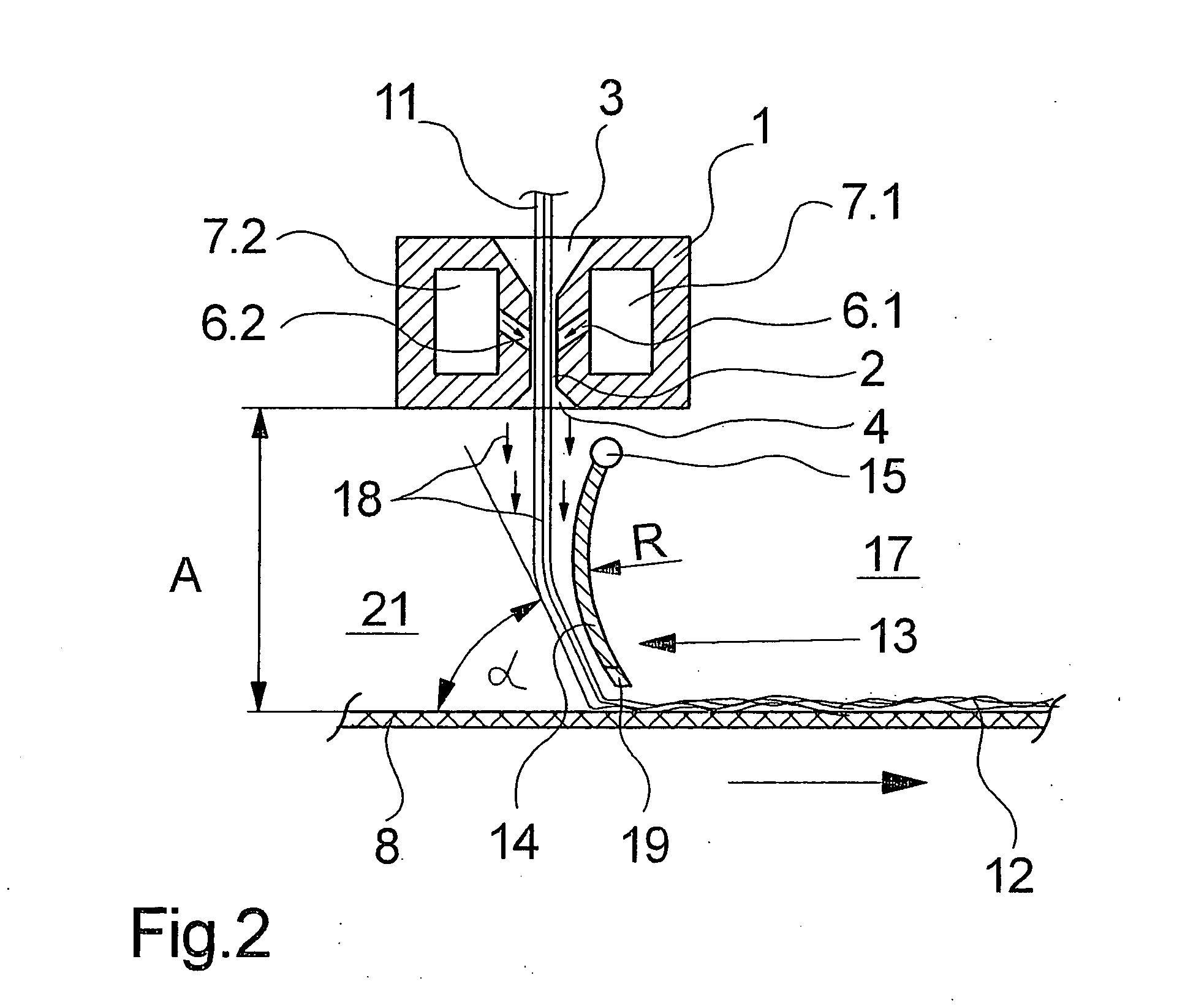
[0031]FIGS. 1 and 2 illustrate a first embodiment of apparatus according to the present invention for depositing synthetic filaments to form a non-woven web. FIG. 1 schematically illustrates the embodiment in one view and FIG. 2 schematically illustrates the embodiment in its cross-sectional view. As long as no reference is made to any of the Figures, the following description shall hold good for both the Figures.

[0032] The illustrated embodiment comprises a drawing unit 1 that is usually arranged below a spinneret. Such drawing units are generally known and are explained in more detail in, for example, the U.S. Pat. No. 6,183,684 B1. In this respect, reference can be made to the mentioned document for a more detailed description and only its essential components are mentioned below.

[0033] The drawing unit 1 comprises a central guide channel 2 that includes a filament inlet 3 at its upper end and a filament outlet 4 at its lower end. The guide channel 2 is designed with a slot sha...


PUM

PropertyMeasurementUnit
Pressureaaaaaaaaaa
Angleaaaaaaaaaa
Angleaaaaaaaaaa

Abstract

A method and apparatus for depositing synthetic filaments to form a non-woven web, wherein the filaments are drawn off from a spinneret through a drawing unit in a row-shaped arrangement using a feed fluid, accelerated into a guide channel and blown out as a filament stream toward an advancing deposit belt. The filament stream is deflected immediately before it impacts upon the deposit belt unilaterally in the advancing direction of the deposit belt in such a way that the filaments impact upon the deposit belt at an angle of <90°. For this purpose, a deflecting means is mounted immediately above the deposit belt.

Description

BACKGROUND OF THE INVENTION [0001] The present invention relates to a method and apparatus for forming a non-woven web by deposition of synthetic filaments upon an advancing deposit felt. [0002] In the manufacturing process of a non-woven web out of synthetic fibers or filaments, a plurality of extruded filament strands have to be deposited to form a textile web as evenly as possible. The filament strands are drawn off using a feed fluid more or less after the extrusion and cool-down processes and guided to a deposit belt. For example, a generic method and also a generic apparatus are described in the U.S. Pat. No. 6,183,684, where a drawing unit is used in order to pull off the synthetic filaments from a spinneret after the extrusion process, and then draw and deposit them. For this purpose, the drawing unit comprises a guide channel that has a slot-shaped filament inlet on its top side and a slot-shaped filament outlet on its lower side. Just below the filament inlet, several flui...

Claims


Application Information

Patent Timeline
IPC IPC(8): D01D5/088B29C47/60D04H3/03D04H3/16
CPCD04H3/03D04H3/16
Inventor STUNDL, MATHIASGRONER-ROTHERMEL, MATHIAS
Owner SAURER GMBH & CO KG
Why Eureka
Try Eureka