Eureka AIR delivers breakthrough ideas for toughest innovation challenges, trusted by R&D personnel around the world.

Wearable electronic device, method for manufacturing portable device, and portable device

a technology of electronic devices and portable devices, which is applied in the field of wearable electronic devices, portable devices, and methods for manufacturing portable devices, can solve the problems of difficulty in making them thinner, difficulty in achieving normal sealed state, and difficulty in reducing thickness, and achieve excellent results. , the effect of increasing air tightness and water tightness

Inactive Publication Date: 2006-09-14
SEIKO EPSON CORP
View PDF0 Cites 71 Cited by
  • Summary
  • Abstract
  • Description
  • Claims
  • Application Information

AI Technical Summary

Benefits of technology

[0013] In this wearable electronic device, the thickness can be reduced because the display panel and the drive circuit are provided to mutually different circuit boards, and the circuit boards are disposed along the peripheral surface of the frame body so as not to be superposed on each other, or the display panel and the drive circuit are both provided to one circuit board without being superposed on each other and are disposed along the peripheral surface of the frame body.
[0024] In the method for manufacturing a portable device made by superposing and mounting the two case bodies in accordance with the present invention, excellent results can be achieved because the device can be assembled unimpeded, regardless of the curved shapes of the case bodies.

Problems solved by technology

However, the problem with these wristwatch-type electronic devices and bracelet-style electronic devices is that they have a thick display unit and it is difficult to make them thinner.
In this case, problems may not occur in cases in which the range of center angles of the two case bodies is small, but if the range of center angle of the two case bodies is large, then problems are encountered when the two case bodies are superposed.
In this case the surfaces around the ends of the case bodies scrape against and scratch each other, or the packing near the ends deforms due to the stress in the direction of curvature along the front surface or the back surface, and breaks out of the packing box, making it impossible to achieve a normal sealed state.

Method used


Image

  • Wearable electronic device, method for manufacturing portable device, and portable device
  • Wearable electronic device, method for manufacturing portable device, and portable device
  • Wearable electronic device, method for manufacturing portable device, and portable device

Examples


first embodiment

[0042] In the present embodiment, a wrist-worn electronic device, which is one aspect of the portable device, will be described.

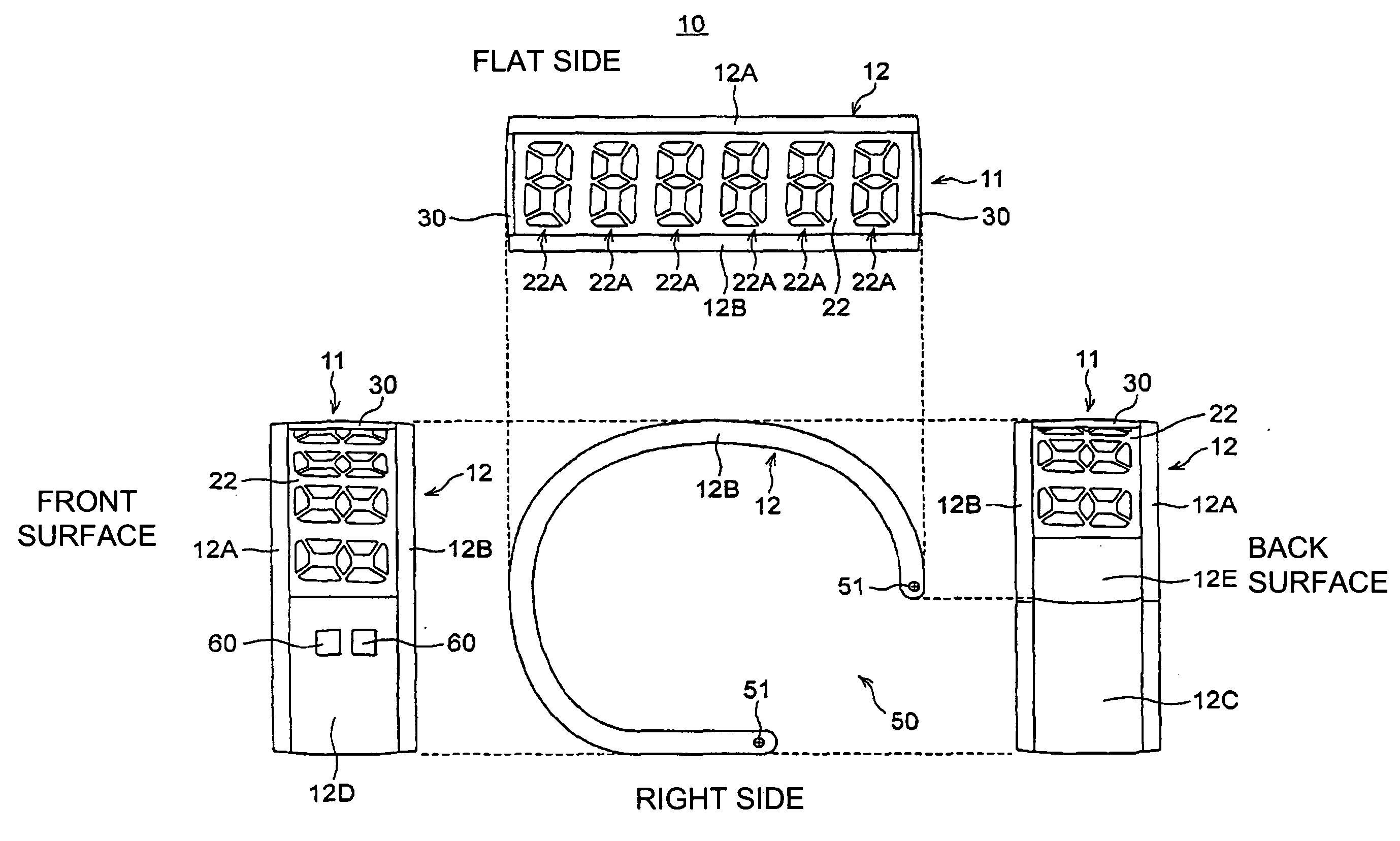
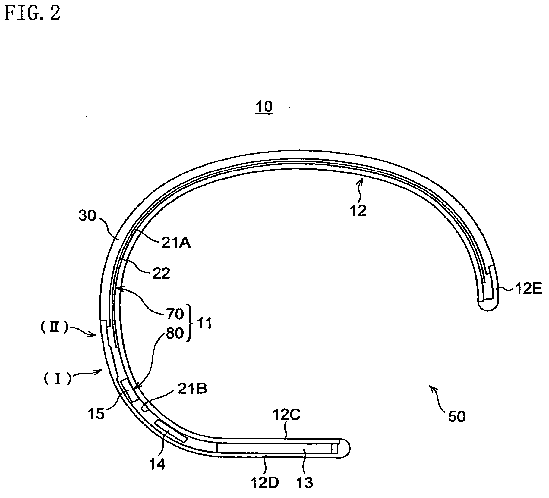
[0043]FIG. 1 is a four-sided view showing a right side view, a plan view, a front view, and a back view of a wrist-worn electronic device 10 according to the present embodiment, and FIG. 2 is a cross-sectional view of the wrist-worn electronic device 10. As shown in these diagrams, the wrist-worn electronic device 10 includes a display unit 11 and a frame body 12.

[0044] The frame body 12 is formed into a substantial C-shape in cross section, has a separated part 50 for fitting onto the arm or wrist of the user when mounted, and includes a left-side frame body 12A and right-side frame body 12B, a back lid 12C, and exterior bodies 12D and 12E, as shown in FIGS. 1 and 2.

[0045] The left-side frame body 12A and the right-side frame body 12B are frames that constitute the left and right sides of the wrist-worn electronic device 10, and the display unit 11 is h...

second embodiment

[0071] Next, the second embodiment of the present invention will be described in detail.

[0072] In this embodiment, a method for manufacturing the wrist-worn electronic device 10 described in the first embodiment or another portable device (electronic device), and a portable device manufactured by implementing this manufacturing method are described.

[0073]FIG. 7 is a schematic perspective view showing the structure of a portable device manufactured according to an embodiment of the method for manufacturing a portable device according to the present invention, FIG. 8 is a longitudinal cross-sectional view showing a cross section along the direction of curvature of the same portable device, and FIGS. 9(a) to 9(e) are cross-sectional views showing the cross-sectional structures of the portions Sa to Se shown in FIG. 2. This portable device 110 is a wearable device that is used while worn by a person, and is also an electronic device equipped with electric circuits in the interior. Mor...


PUM


Abstract

The device has a frame body (12) that has a substantial C-shape in cross section and is mounted on the body of a user, a strip-shaped display panel (22) disposed along the peripheral surface of the frame body (12), and a driver IC (15) for driving the display panel (22), wherein the display panel (22) and the driver IC are provided to different flexible substrates (21A, 21B), and the flexible substrates (21A, 21B) are disposed along the peripheral surface of the frame body (12) without being superposed on each other.

Description

FIELD OF THE INVENTION [0001] The present invention relates to a wearable electronic device that is mounted on the wrist or the like of a user that is configured to be capable of displaying various information, to a method for manufacturing a portable device, and to a portable device; and the present invention particularly relates to a wrist-mounted portable device, or to a technique for manufacturing a device that is suitable as a portable display device. BACKGROUND OF THE INVENTION [0002] Commonly known prior-art examples of electronic devices that are mounted on the wrist or the like of a user that have a display unit for displaying various types of information include wristwatches, diver's computers, and other such wrist-mounted portable devices (electronic devices). Most wrist-mounted portable devices include a main body having a display unit, and a band connected to the main body. The band is made of metal, leather, or the like, and is configured to hold the main body to the w...

Claims


Application Information

Patent Timeline
IPC IPC(8): A01K7/00
CPCG04B37/12G04G17/083
Inventor ISHII, JUNICHIROARAI, SHUNICHITAKAHASHI, KAZUTOSHI
Owner SEIKO EPSON CORP
Why Eureka
Eureka Blog
Learn More