Liquid crystal display device

a liquid crystal display and display device technology, applied in non-linear optics, instruments, optics, etc., can solve the problems of narrow viewing angle characteristic range and reduced transmittance, and achieve the effect of reducing cost and improving viewing angle characteristics

Inactive Publication Date: 2006-09-14
TOSHIBA MATSUSHITA DISPLAY TECH
View PDF3 Cites 122 Cited by
  • Summary
  • Abstract
  • Description
  • Claims
  • Application Information

AI Technical Summary

Benefits of technology

[0014] The present invention has been made in consideration of the above-described problems, and the object of the invention is to provide a liquid crystal display device that can improve viewing angle characteristics and can reduce cost.
[0017] The present invention can provide a liquid crystal display device that can improve viewing angle characteristics and can reduce cost.

Problems solved by technology

In a linear-polarization-based, birefringence-controlled liquid crystal display device, such a problem arises that transmittance is lowered in a region where liquid crystal molecules are oriented in a direction other than a desirable direction.
In the prior-art circular-polarization-based MVA mode, however, there is such a problem that the viewing angle characteristic range is narrow.

Method used


Image

  • Liquid crystal display device
  • Liquid crystal display device
  • Liquid crystal display device

Examples


embodiment 1

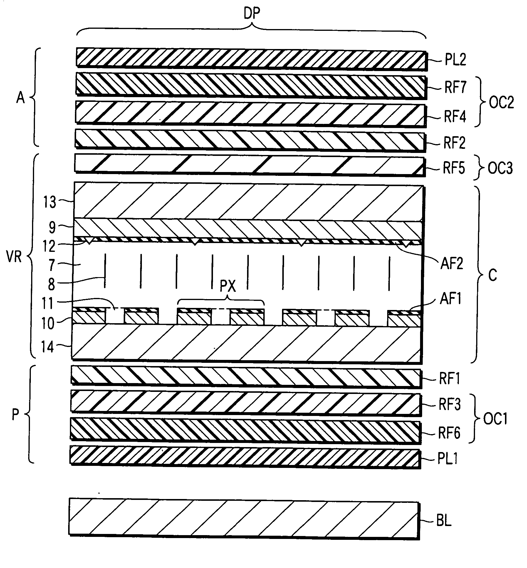
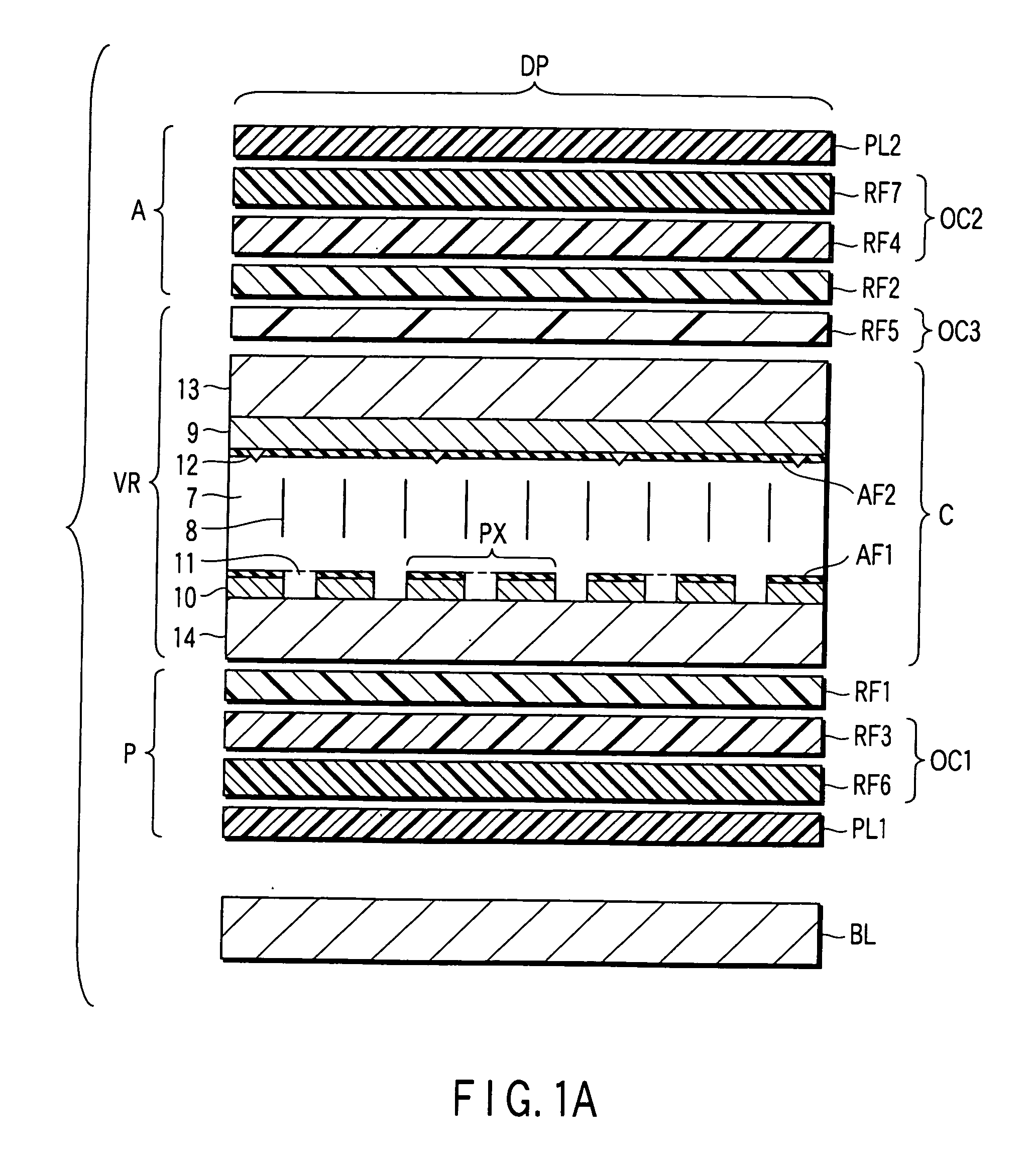
[0100] In a liquid crystal display device according to Embodiment 1, an F-based liquid crystal (manufactured by Merck Ltd.) was used as a nematic liquid crystal material with negative dielectric anisotropy for the liquid crystal layer 7. The refractive index anisotropy Δn of the liquid crystal material used in this case is 0.095 (wavelength for measurement=550 nm; in the description below, all refractive indices and phase differences of retardation plates are values measured at wavelength of 550 nm), and the thickness d of the liquid crystal layer 7 is 3.5 μm. Thus, the Δn·d of the liquid crystal layer 7 is 330 nm.

[0101] In Embodiment 1, a uniaxial ¼ wavelength plate (in-plane phase difference=140 nm), which is formed of ZEONOR resin (manufactured by Nippon Zeon Co., Ltd.), is used as the first retardation plate RF1 and second retardation plate RF2. An alignment film, which is formed of JALS214-R14 (manufactured by JSR), is provided on the surface (opposed to the polarizer plate) o...

embodiment 2

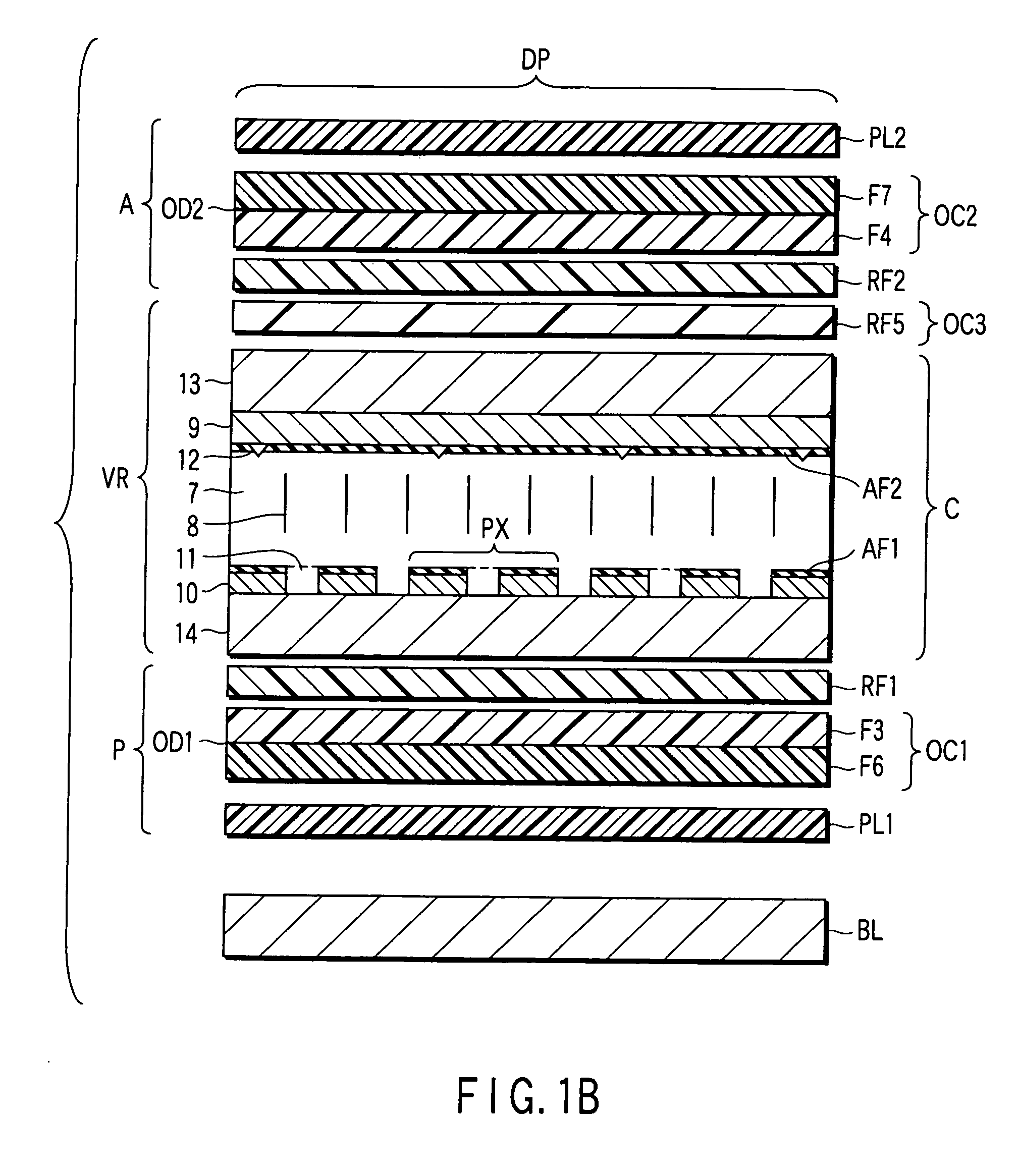
[0108] The structure of a liquid crystal display device according to Embodiment 2 is the same as the structure of the liquid crystal display device according to Embodiment 1, except that the fifth retardation plate RF5 is composed of two segments, as shown in FIG. 1C.

[0109] Specifically, in Embodiment 2, a liquid crystal polymer layer, which functions as the third retardation plate RF3, is formed on the surface (opposed to the polarizer plate) of the film used as the first retardation plate RF1. On the other hand, the back surface (opposed to the liquid crystal cell C) of the film that is used as the first retardation plate RF1 is rubbed, and the rubbed surface is coated with an ultraviolet cross-linking chiral nematic liquid crystal (manufactured by Merck Ltd.) with a thickness of 1.18 μm, which has a refractive index anisotropy Δn of 0.102 and a helical pitch of 0.9 μm. The coated liquid crystal polymer layer is irradiated with ultraviolet in the state in which the helical axis a...

embodiment 3

[0114] In a liquid crystal display device according to Embodiment 3, an F-based liquid crystal (manufactured by Merck Ltd.) was used as a nematic liquid crystal material with negative dielectric anisotropy for the liquid crystal layer 7. The refractive index anisotropy Δn of the liquid crystal material used in this case is 0.095 (wavelength for measurement=550 nm; in the description below, all refractive indices and phase differences of retardation plates are values measured at wavelength of 550 nm), and the thickness d of the liquid crystal layer 7 is 3.5 μm. Thus, the Δn·d of the liquid crystal layer 7 is 330 nm.

[0115] In Embodiment 3, a uniaxial ¼ wavelength plate (in-plane phase difference=140 nm), which is formed of ZEONOR resin (manufactured by Nippon Zeon Co., Ltd.), is used as the first retardation plate RF1 and second retardation plate RF2. A vertical alignment film, which is formed of JALS214-R14 (manufactured by JSR), is provided on the surface (opposed to the polarizer ...


PUM

PropertyMeasurementUnit
¼ wavelengthaaaaaaaaaa
thicknessaaaaaaaaaa
thicknessaaaaaaaaaa

Abstract

A circular-polarization-based vertical alignment mode liquid crystal display device includes a circular polarizer structure, a variable retarder structure and a circular analyzer structure. The circular polarizer structure includes a first optical compensation layer for optical compensation thereof, the first optical compensation layer including a uniaxial retardation plate with a refractive index anisotropy of nx≈ny<nz. The circular analyzer structure includes a second optical compensation layer for optical compensation thereof, the second optical compensation layer including a uniaxial retardation plate with a refractive index anisotropy of nx≈ny<nz. The variable retarder structure includes a third optical compensation layer for optical compensation thereof, the third optical compensation layer including a uniaxial retardation plate with a refractive index anisotropy of nx≈ny>nz.

Description

CROSS-REFERENCE TO RELATED APPLICATIONS [0001] This application is based upon and claims the benefit of priority from prior Japanese Patent Application No. 2005-064128, filed Mar. 8, 2005, the entire contents of which are incorporated herein by reference. BACKGROUND OF THE INVENTION [0002] 1. Field of the Invention [0003] The present invention relates generally to a liquid crystal display device, and more particularly to a circular-polarization-based vertical-alignment-mode liquid crystal display device. [0004] 2. Description of the Related Art [0005] A liquid crystal display device has various features such as thickness in size, light weight, and low power consumption. The liquid crystal display device is applied to various uses, e.g. OA equipment, information terminals, timepieces, and TVs. In particular, a liquid crystal display device comprising thin-film transistors (TFTs) has high responsivity and, therefore, it is used as a monitor of a mobile TV, a computer, etc., which disp...

Claims


Application Information

Patent Timeline
Patent Type & Authority Applications(United States)
IPC IPC(8): G02F1/1335
CPCG02F1/13363G02F1/1393G02F2001/133541G02F2413/04G02F1/133541
Inventor ITO, HIDEKIMURAYAMA, AKIOHISATAKE, YUUZOTAGO, CHIGUSA
Owner TOSHIBA MATSUSHITA DISPLAY TECH
Why Eureka
Try Eureka