Methods and apparatus for implementing and using a maximum rate option indicator

a technology of maximum rate and indicator, applied in the direction of wireless communication, wireless commuication services, multiplex communication, etc., can solve the problems of low efficiency of approach, low power utilization of wireless terminals, and relatively high transmission rates

Active Publication Date: 2006-09-14
QUALCOMM INC
View PDF28 Cites 45 Cited by
  • Summary
  • Abstract
  • Description
  • Claims
  • Application Information

AI Technical Summary

Benefits of technology

[0014] In some embodiments, using first and second types of maximum rate option indicators, different modulation methods are used to transmit first and second maximum uplink rate option indicator values. For example, some embodiments use a first type maximum uplink rate option indicator which is communicated as part of a first type of assignment, e.g., a flash assignment, using a non-coherent modulation method such as, e.g., a modulation method using a combination of zero and non-zero QPSK modulation symbols, while a second type of maximum uplink rate option indicator is communicated as part of a second type of assignment, e.g., a regular assignment, using a coherent modulation method using QPSK modulation symbols. In some such embodiments, the non-zero modulation symbols of the first type of assignments are communicated using a higher power level than the modulation symbols of the second type of assignment.
[0015] In various embodiments, the base station transmits assignments including maximum rate indicators according to a predetermined periodic transmission schedule having a fixed timing relationship to the uplink segments being assigned. In some embodiments, each first type of maximum uplink rate option indicator is communicated in an assignment message including at most one uplink communication segment assignment, while a second type of maximum rate option indicator is communicated in communicated in an assignment message including one or more, e.g., two, maximum uplink communications segment assignments, e.g., with each separate assigned uplink communications segment having a corresponding separate uplink rate option indicator.

Problems solved by technology

However, at a low coding rate, the wireless terminal may use a relatively low level of power and transmit a relatively small number of user data / information bits per total bits and a relatively high number of error correcting or redundant information bits per total number of bits.
This approach is not very efficient as the base station has limited knowledge of the wireless terminal's condition at the time of uplink data transmission rate assignment.
However, the base station has an incomplete set of information as to determine what uplink data rate the wireless terminal should use at the time of its uplink transmission.
Typically, this results in operational inefficiencies.
This results in the wireless terminal unnecessarily consuming valuable battery energy and creating a higher level of interference in the system than if it had transmitted at the lower data rate which would have satisfied its needs.
This contributes to latency delays in the system.
In many cases it is not practical, effective, or convenient to convey such information to a base station, e.g., either from an overhead standpoint or from a time latency standpoint or such information to the extent that it is conveyed is somewhat out of date by the time it arrives at the base station.

Method used


Image

  • Methods and apparatus for implementing and using a maximum rate option indicator
  • Methods and apparatus for implementing and using a maximum rate option indicator
  • Methods and apparatus for implementing and using a maximum rate option indicator

Examples


Embodiment Construction

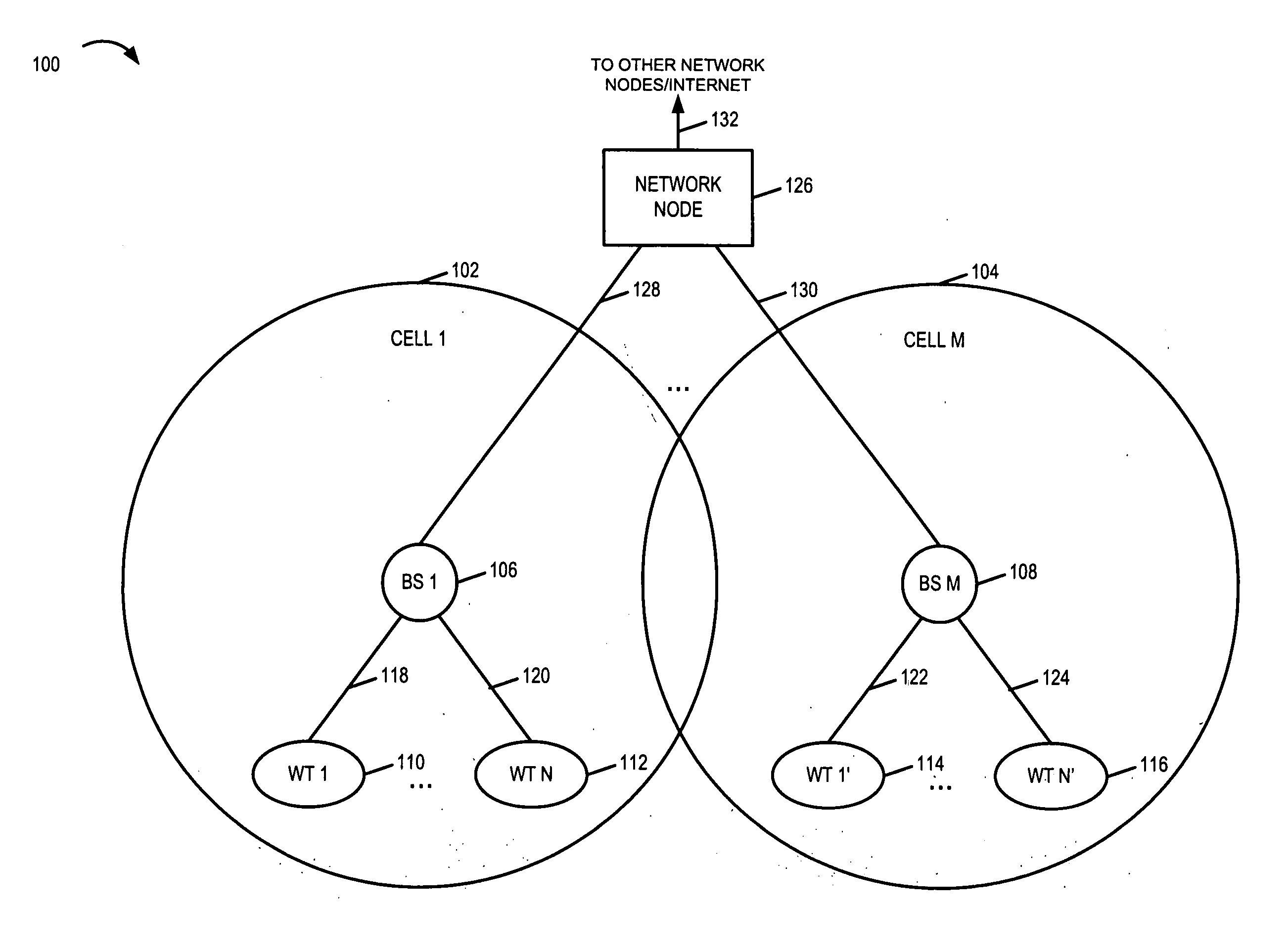
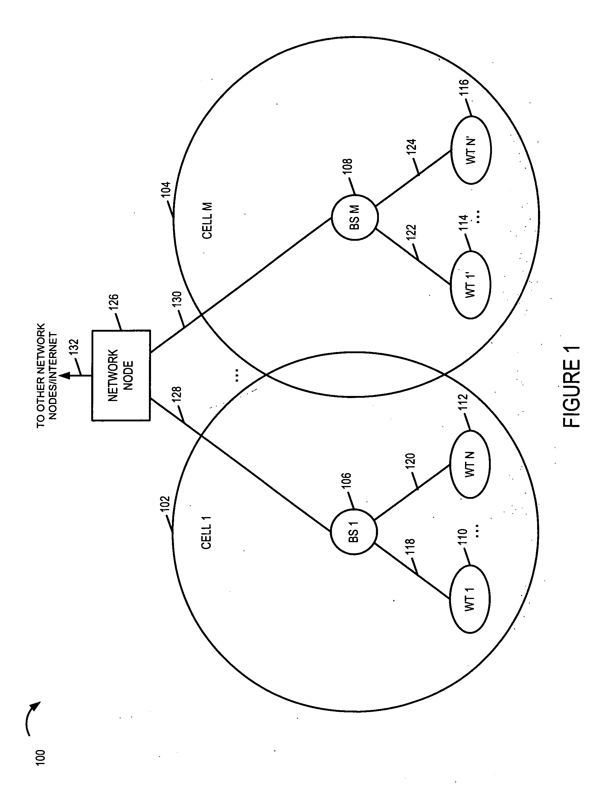
[0053]FIG. 1 is a drawing of an exemplary communications system 100, implemented in accordance with the present invention and using methods of the present invention. System 100 includes apparatus and methods directed to improving uplink communications by selecting and communicating uplink data rate information. Exemplary system 100 may be, e.g., an orthogonal frequency division multiplexing (OFDM) multiple access wireless communication system. System 100 includes a plurality of cells (cell 1102, cell M 104). Each cell (cell 1102, cell M 104) represents a wireless coverage area for a corresponding base station (BS 1106, BS M 108), respectively. A plurality of wireless terminal (WTs) (WT 1110, WT N 112, WT 1′114, WT N′116) are included in system 100. At least some of the WTs are mobile nodes (MNs); the MNs may move throughout the system 100 and establish wireless links with different BSs, the BS corresponding to the cell in which the WT is currently located. In FIG. 1, (WT 1110, WT N ...


PUM


Abstract

A base station selects a maximum rate option indicator value for an uplink communications segment, e.g., uplink traffic channel segment, and transmits the selected indicator value, e.g., as part of the assignment message. The maximum rate option indicator value indicates to the wireless terminal a maximum allowed data rate option that the wireless terminal is permitted to use for the corresponding assigned uplink communications segment, the wireless terminal determining the actual uplink rate option used. Each uplink data rate option corresponds to: a number of information bits to be communicated in an uplink communication segment, a coding rate, and a modulation method. Some embodiments include multiple types of maximum uplink rate option indicators, e.g., a first type using a single bit and a second type using at least three bits. Different modulation methods are, in some embodiments, used for communicating the different types of maximum uplink rate option indicators.

Description

RELATED APPLICATIONS [0001] The present application claims the benefit of U.S. Provisional Patent Application Ser. No. 60 / 659,502, filed on Mar. 8, 2005, titled “METHOD AND APPARATUS FOR IMPLEMENTING AND USING AN UPLINK RATE INDICATOR”, U.S. Provisional Patent Application Ser. No. 60 / 701,469, filed on Jul. 20, 2005, titled “METHODS AND APPARATUS FOR SIGNALING UPLINK DATA RATE OPTION INFORMATION”, U.S. Provisional Patent Application Ser. No. 60 / 701,434, filed on Jul. 20, 2005, titled “METHODS AND APPARATUS FOR WIRELESS TERMINAL UPLINK DATA RATE OPTION SELECTION”, and U.S. Provisional Patent Application Ser. No. 60 / 701,468, filed on Jul. 20, 2005, titled “METHODS AND APPARATUS FOR IMPLEMENTING AND USING A MAXIMUM UPLINK RATE OPTION INDICATOR”, each of which is hereby expressly incorporated by reference.FIELD OF THE INVENTION [0002] The present invention relates to methods and apparatus for improving the uplink communications for wireless communication devices, and more particularly to...

Claims


Application Information

Patent Timeline
Patent Type & Authority Applications(United States)
IPC IPC(8): H04Q7/00H04W28/22
CPCH04W28/22
Inventor LAROIA, RAJIVJIN, HUIRICHARDSON, TOMLI, JUNYI
Owner QUALCOMM INC
Why Eureka
Try Eureka