
Apparatus for providing optical radiation

a technology of optical radiation and optical beam, applied in the direction of lasers, instruments, active medium shape and construction, etc., can solve the problem of relatively low energy storage capacity

Active Publication Date: 2006-09-14
SPI LASERS UK
View PDF8 Cites 70 Cited by
  • Summary
  • Abstract
  • Description
  • Claims
  • Application Information

AI Technical Summary

Problems solved by technology

Their disadvantage is their relatively low energy storage capacity as compared to NdYAG lasers.

Method used


Image

  • Apparatus for providing optical radiation
  • Apparatus for providing optical radiation
  • Apparatus for providing optical radiation

Examples


Embodiment Construction

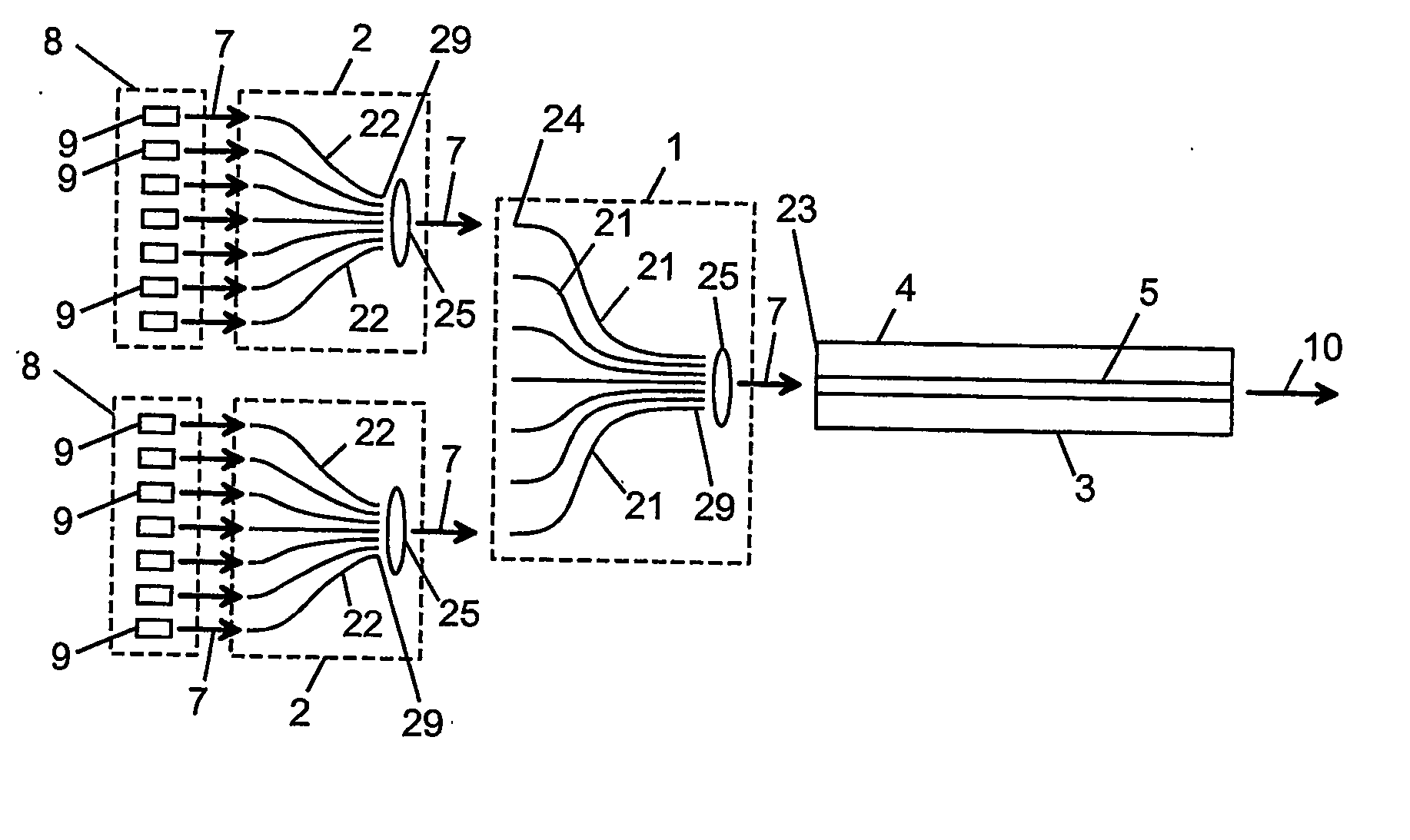
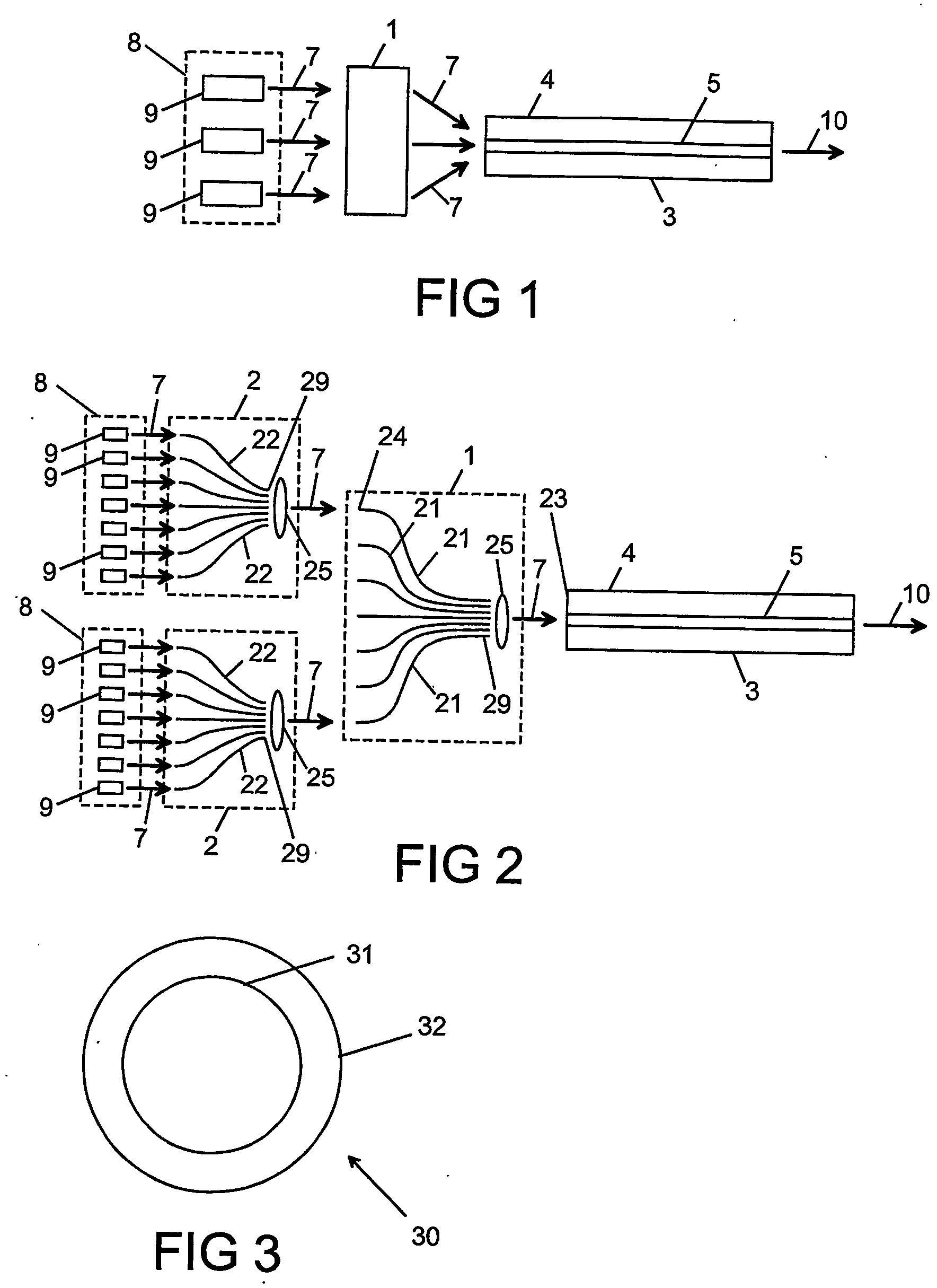
[0049] With reference to FIG. 1, there is provided apparatus for providing optical radiation 10 comprising a pump array 8 for providing pump radiation 7, a first pump combiner 1, and a waveguide 3, wherein the pump radiation 7 from the pump array 8 is coupled into the waveguide 3 via the first pump combiner 1, and wherein the waveguide 3 comprises a pump guide 4 for guiding the pump radiation 7, and a gain medium 5 which emits the optical radiation 10 when it is pumped by the pump radiation 7.

[0050] The pump array 8 shown in FIG. 1 comprises a plurality of pumps 9. There is shown in FIG. 2 apparatus comprising a plurality of pump arrays 8 and a plurality of second pump combiners 2. The pump radiation 7 emitted by each of the pump arrays 8 is combined together by different ones of the second pump combiners 2. The first pump combiner 1 is shown comprising an array of first pump waveguides 21. The first pump waveguides 21 may be optical fibre waveguides. Pump radiation 7 is coupled be...


PUM


Abstract

Apparatus for providing optical radiation (10) comprising a pump array (8) for providing pump radiation (7), a first pump combiner (1), and a waveguide (3), wherein the pump radiation (7) from the pump array (8) is coupled into the waveguide (3) via the first pump combiner (1), and wherein the waveguide (3) comprises a pump guide (4) for guiding the pump radiation (7), and a gain medium (5) which emits the optical radiation (10) when it is pumped by the pump radiation (7).

Description

FIELD OF INVENTION [0001] This invention relates to an apparatus for providing optical radiation. The apparatus can take various forms, for example a laser, a Q-switched laser, or a master oscillator power amplifier. The invention has application for materials processing. BACKGROUND TO THE INVENTION [0002] Pulsed neodymium yttrium aluminium garnet (NdYAG) lasers are widely used in industrial processes such as welding, cutting and marking. Care has to be taken in these processes to ensure that the plasmas generated by the laser does not interfere with the incoming laser pulses. The relatively low pulse repetition rates (6 kHz) at high peak powers that are achievable in a NdYAG laser have led to their wide application in laser machining. [0003] Fibre lasers are increasingly being used for materials processing applications such as welding, cutting and marking. Their advantages include high efficiency, robustness and high beam quality. Examples include femtosecond lasers for multiphoton...

Claims


Application Information

Patent Timeline
IPC IPC(8): G02B6/02G02B6/42H01S3/067H01S3/094
CPCG02B6/4201G02B6/4206H01S3/067H01S3/06729H01S3/06741H01S3/094003H01S3/094015H01S3/094019H01S3/094042H01S3/094061H01S3/09408H01S3/2383
Inventor CLARKSON, WILLIAM ANDREWPAYNE, DAVID NEILVARNHAM, MALCOLM PAULZERVAS, MIKHAIL NICHOLAOS
Owner SPI LASERS UK
Features
  • Generate Ideas
  • Intellectual Property
  • Life Sciences
  • Materials
  • Tech Scout
  • Unparalleled Data Quality
  • Higher Quality Content
  • 60% Fewer Hallucinations
Learn More