
Torque changeable pivot

Inactive Publication Date: 2006-09-14
QUANTA COMPUTER INC
View PDF7 Cites 0 Cited by
  • Summary
  • Abstract
  • Description
  • Claims
  • Application Information

AI Technical Summary

Benefits of technology

[0007] Another object of the invention is to provide a torque changeable pivot that helps simplify the management of materials using standardized elements.
[0008] A further object of the invention is to provide a torque changeable pivot whose torque value is switched according to whether a pin is inserted during the production. It is less likely to put a wrong pivot due to mixed materials.
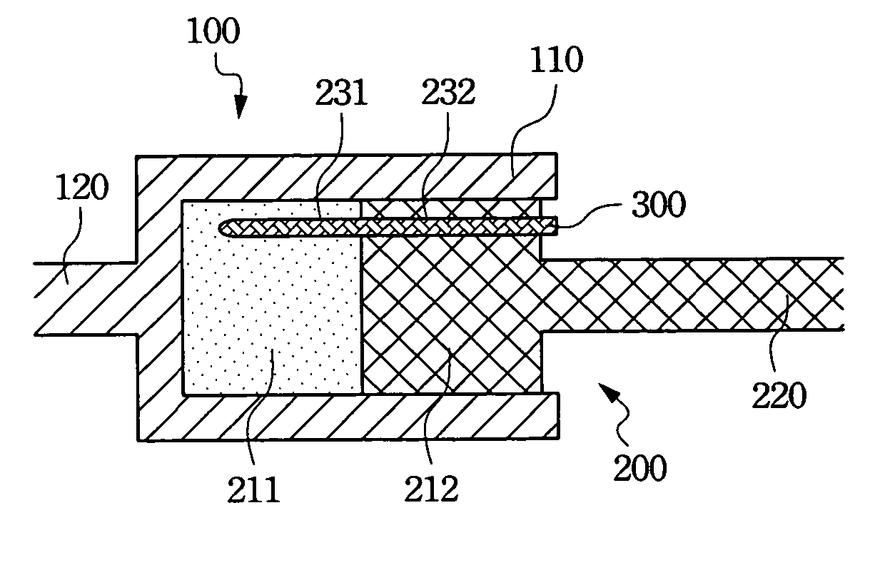
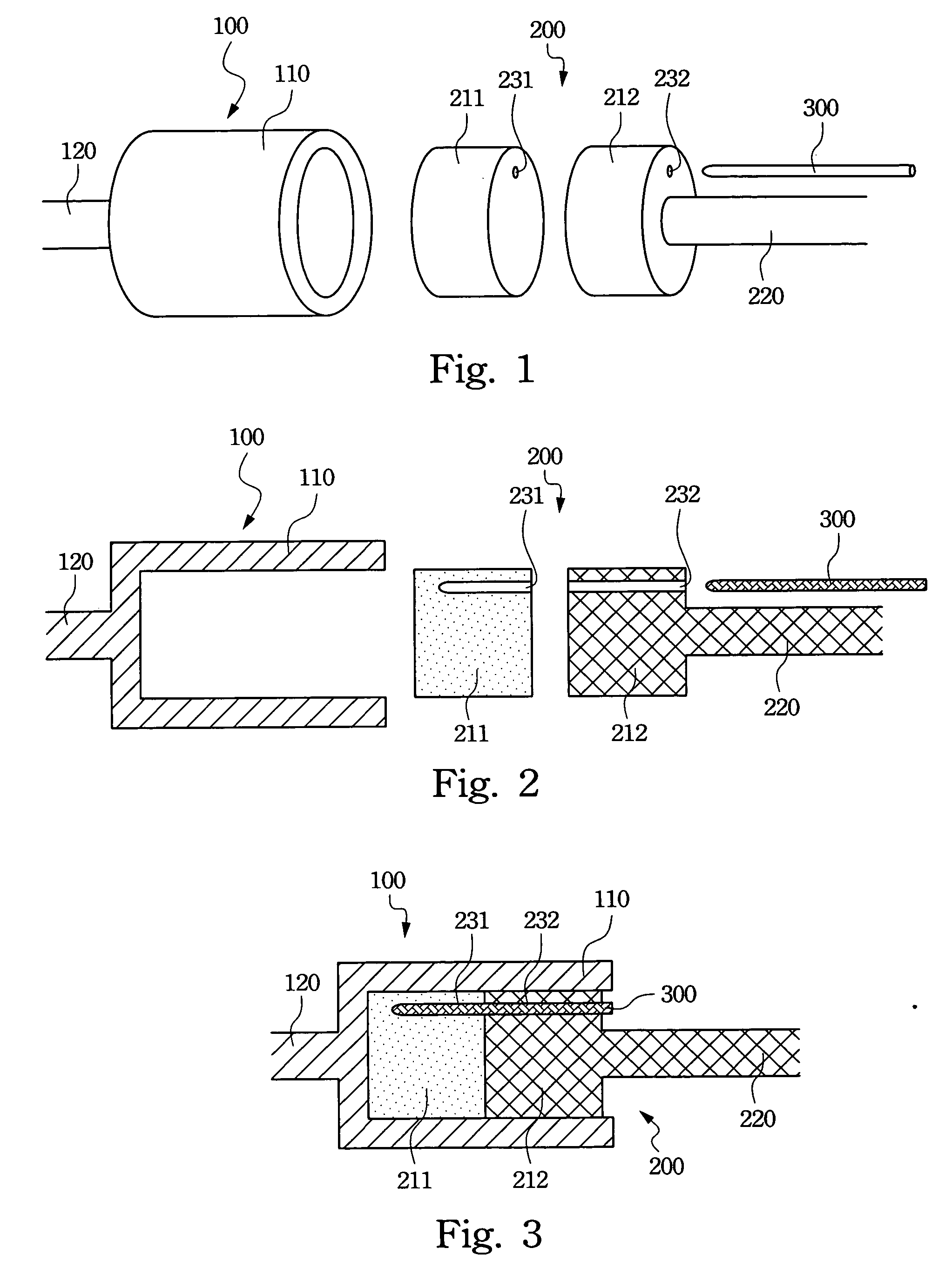
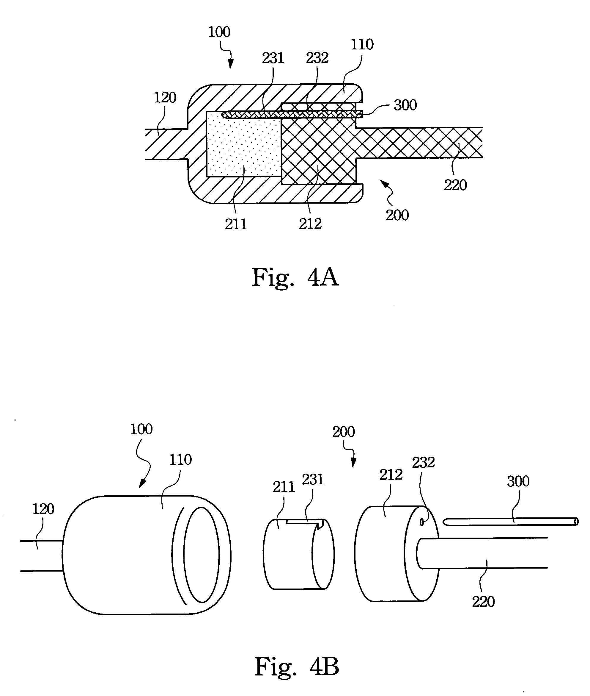
[0009] According to the above-mentioned objects, the disclosed torque changeable pivot includes a cylinder, a spindle, and a pin. The cylinder further includes a cylinder shell and the spindle further includes a first rotational portion and a second rotational portion. A peripheral surface of the first rotational portion couples to an inner surface of the cylinder shell and the first rotational portion further includes a first coupling member eccentrically disposed on the first rotational portion. A peripheral surface of the second rotational portion couples to the inner surface of the cylinder shell and the second rotational portion further includes a second coupling member eccentrically disposed on the second rotational portion. When the first coupling member is aligned with the second coupling member and the pin is inserted into the first coupling member and the second coupling member, the first rotational portion and the second rotational portion are combined together. Therefore, the torque of the torque changeable pivot is increased.

Problems solved by technology

Insufficient torque will result in a loose support for the display screen.
If the torque is too large, it will be difficult to adjust the angle of the screen.
However, the conventional pivots always provide unchangeable torques and cannot meet these requirements.
It is thus a trouble for material management.
Sometimes, wrong pivots will be used and result in a low yield.
This inevitably increases the production cost.

Method used


Image

  • Torque changeable pivot
  • Torque changeable pivot
  • Torque changeable pivot

Examples


Embodiment Construction

[0023] The present invention will be apparent from the following detailed description, which proceeds with reference to the accompanying drawings, wherein the same references relate to the same elements.

[0024] As shown in FIGS. 1, 2, and 3, the disclosed torque changeable pivot includes a cylinder 100, a spindle 200, and a pin 300. The cylinder 100 and the spindle 200 are coupled together using the same axis of the pivot.

[0025] The cylinder 100 includes a cylinder shell 110 and a rotational axis 120. The cylinder shell 110 is an axially symmetric cylinder. The bottom of the cylinder shell is perpendicular to the axis of the pivot in a preferred embodiment of the invention. The rotational axis 120 is coupled to the bottom of the cylindrical structure of the cylinder shell 110, extending outward from the pivot. As the rotational axis 120 rotates, the cylinder shell 110 rotates along the rotational axis 120. For different pivots, the invention can eccentrically couple the rotational ...


PUM


Abstract

A torque changeable pivot is described. The torque changeable pivot includes a cylinder, a spindle, and a pin. The cylinder further includes a cylinder shell and the spindle further includes a first rotational portion and a second rotational portion. A peripheral surface of the first rotational portion couples to an inner surface of the cylinder shell and the first rotational portion further includes a first coupling member eccentrically disposed on the first rotational portion. A peripheral surface of the second rotational portion couples to the inner surface of the cylinder shell and the second rotational portion further includes a second coupling member eccentrically disposed on the second rotational portion. When the first coupling member is aligned with the second coupling member and the pin is inserted into the first coupling member and the second coupling member, the first rotational portion and the second rotational portion are combined together.

Description

RELATED APPLICATIONS [0001] The present application is based on, and claims priority from, Taiwan Application Serial Number 94107335, filed Mar. 10, 2005, the disclosure of which is hereby incorporated by reference herein in its entirety. BACKGROUND OF THE INVENTION [0002] 1. Field of Invention [0003] The invention relates to a pivot and, in particular, to a torque changeable pivot used in computer manufacturing processes. [0004] 2. Related Art [0005] The pivot used in a normal laptop computer or thin display has to provide an appropriate torque to support the weight of the screen. Insufficient torque will result in a loose support for the display screen. If the torque is too large, it will be difficult to adjust the angle of the screen. Take the laptop computers as an example, manufacturers may provide display devices of different sizes and weights in a certain series of laptop computers for selection. During the computer manufacturing process, manufacturers usually have to provide...

Claims


Application Information

Patent Timeline
IPC IPC(8): F16C11/00
CPCE05D11/081E05D11/082E05Y2201/21Y10T403/32614E05Y2900/606G06F1/1616G06F1/1681E05Y2201/25E05Y2999/00
Inventor TSAI, WEN-JICHANG, JUNG-WEN
Owner QUANTA COMPUTER INC
Learn More