Bicycle sprocket

a sprocket and bicycle technology, applied in the field of bicycle sprockets, can solve the problems of loss of fastening force between the fastening part and the spider arm (rotating drive unit), so as to prevent the loss of fastening force resulting from deterioration or deformation of synthetic resin, and reduce weight

Active Publication Date: 2006-09-14
SHIMANO INC
View PDF15 Cites 71 Cited by
  • Summary
  • Abstract
  • Description
  • Claims
  • Application Information

AI Technical Summary

Benefits of technology

[0013] One object of the present invention is to provide a bicycle sprocket having a fastening part made of a synthetic resin in which the bicycle sprocket is con

Problems solved by technology

Furthermore, mounting holes with steps are formed in the fastening part of the gear crank.
In the conventional bicycle sprocket previously described, loss of the fastening force between the fastening part and the spider arm (rotating drive unit) can occur as a result of deterioration over time in the synthetic resin constituting the fastening part.
Also, the fastening part made of a synthetic resin deforms if the bolt is fastened with excessive torque, which may of course result in a loss of the fastening fo

Method used


Image

  • Bicycle sprocket
  • Bicycle sprocket
  • Bicycle sprocket

Examples


Embodiment Construction

[0046] Selected embodiments of the present invention will now be explained with reference to the drawings. It will be apparent to those skilled in the art from this disclosure that the following descriptions of the embodiments of the present invention are provided for illustration only and not for the purpose of limiting the invention as defined by the appended claims and their equivalents.

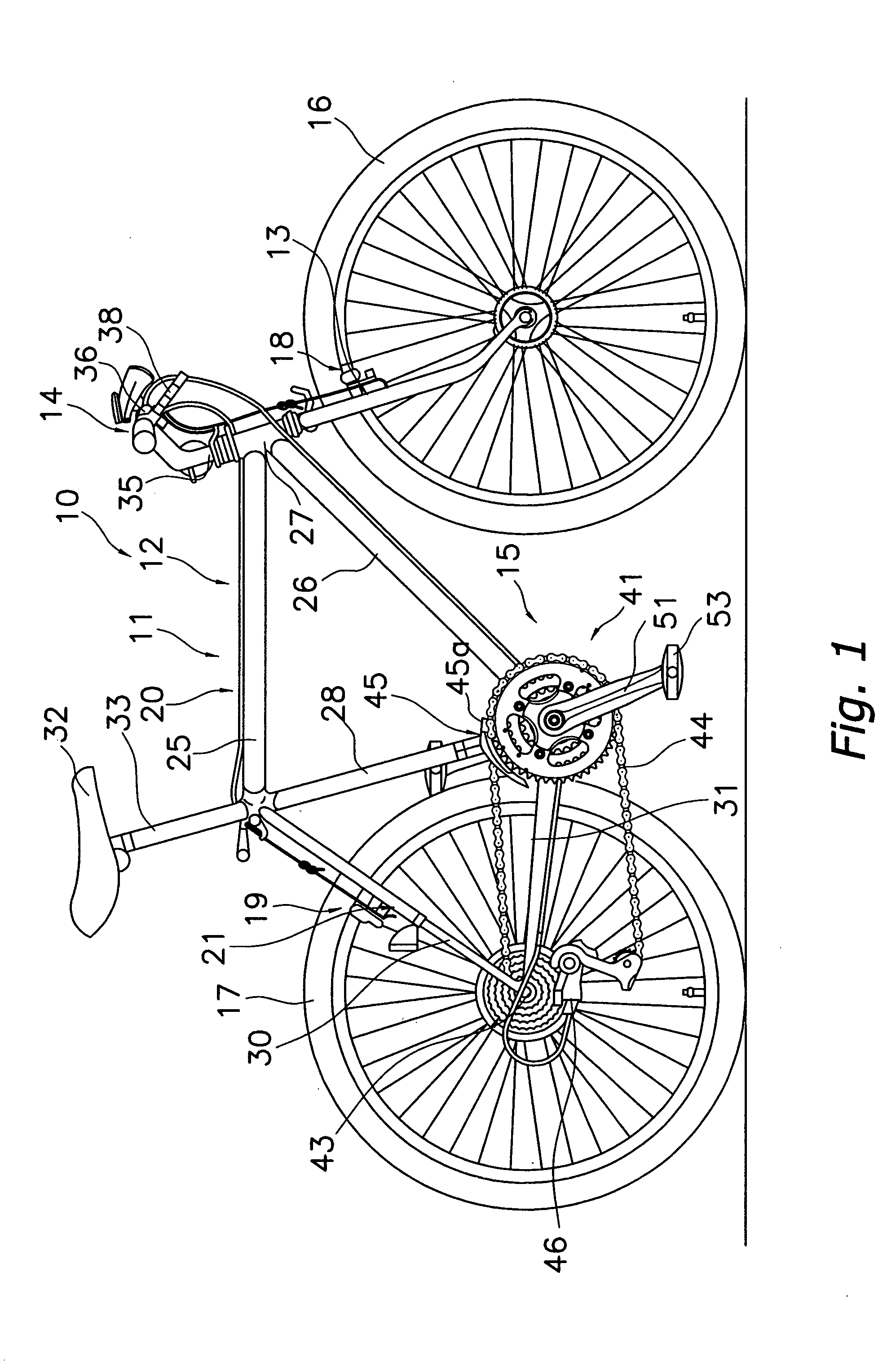
[0047] Referring initially to FIG. 1, a bicycle 10 is illustrated that can be used with each embodiment of the present invention. The bicycle 10 is equipped in accordance with a first embodiment of the present invention. While the bicycle 10 is illustrated as a mountain bike, it will be apparent to those skilled in the art from this disclosure that the present invention can be applied to other types of bicycles such as a road bike. As used herein to describe the present invention, the following directional terms “forward, rearward, above, downward, vertical, horizontal, below and transverse” as w...


PUM


Abstract

A bicycle sprocket basically has a metallic sprocket ring part and a synthetic resin fastening part that is configured to ensure that weight can be reduced and that loss of fastening force resulting from deterioration or deformation of the synthetic resin can be prevented. The metallic sprocket ring part includes a ring element with a plurality of sprocket teeth located on an outer periphery of the ring element, a plurality of connecting elements located on an inner periphery of the ring element and a plurality of internal fastening elements located on radial inner ends of the connecting elements, respectively. The synthetic resin fastening part is non-movably formed on both axial faces of the sprocket ring part at a location radially inwardly of the sprocket teeth so as to cover at least a portion of the inner periphery of the ring element, the connecting elements, and the internal fastening elements.

Description

CROSS-REFERENCE TO RELATED APPLICATIONS [0001] This application claims priority under 35 U.S.C. § 119 to Japanese Patent Application No. 2005-064732. The entire disclosure of Japanese Patent Application No. 2005-064732 is hereby incorporated herein by reference. BACKGROUND OF THE INVENTION [0002] 1. Field of the Invention [0003] This invention generally relates to a sprocket. More specifically, the present invention relates to a bicycle sprocket that is configured to be mounted on the rotating drive unit of a bicycle, and that is configured to engage a bicycle-driving chain that is to be wrapped around the external periphery of the bicycle sprocket. [0004] 2. Background Information [0005] Bicycling is becoming an increasingly more popular form of recreation as well as a means of transportation. Moreover, bicycling has become a very popular competitive sport for both amateurs and professionals. Whether the bicycle is used for recreation, transportation or competition, the bicycle ind...

Claims


Application Information

Patent Timeline
IPC IPC(8): F16H55/30F16H55/12
CPCB62M9/105F16H55/30
Inventor NONOSHITA, TETSUINOUE, HIDEYA
Owner SHIMANO INC
Why Eureka
Try Eureka