Method and device for knit design and program

Inactive Publication Date: 2006-09-14
SHIMA SEIKI MFG LTD
View PDF6 Cites 4 Cited by
  • Summary
  • Abstract
  • Description
  • Claims
  • Application Information

AI Technical Summary

Benefits of technology

[0035] In the knit design method, apparatus, and program according to the present invention, a pattern spread over a plurality of parts is designed on a composite image of the parts. Therefore, the design of the pattern can be carried out easily. Further, at the time of dividing the composite image, the pattern can be suitably assigned to the respective parts. Thus, it is possible to overcome the constraint that the design of only the pattern which falls within an area of one gore can be made without any difficulty, in the case of designing a flared skirt or a sweater in a parachute pattern or the like. Further, it becomes easy to design the pattern spread over both of the body and the sleeve.
[0036] At the time of carrying out correction for the non-uniform narrowing stitches or widening stitches by the shift of the pattern, for example, one of the right and left borders on the upper side or the lower side is shifted by the amount corresponding to the stitch number of the non-uniform narrowing stitches or widening stitches. In particular, if the pattern is shrunk by the shift, the common portion of the shifted left and right borders should be determined as the area of the pattern. For example, the process should be carried out before dividing the composite design image into a plurality of parts.
[0037] Preferably, the shift is carried out after imaginarily assigning the pattern to a plurality of parts such that the portion of each part is shifted by the amount corresponding to the non-uniform narrowing stitches or widening stitches, and by the shift, data of the pattern assi

Problems solved by technology

Usual, but complicated processes such as narrowing stitches, widening stitches, or cast off stitches are formed by storing a subroutine, and retrieving the subroutine from a library.
However

Method used


Image

  • Method and device for knit design and program
  • Method and device for knit design and program
  • Method and device for knit design and program

Examples


second embodiment

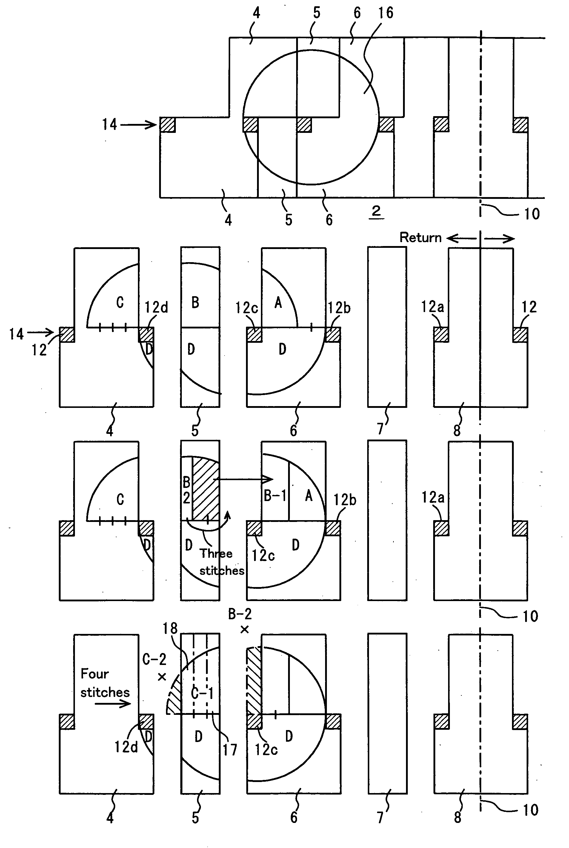
[0089] The overview of processes in the second embodiment is shown in FIG. 8. In FIG. 8, the constituent elements that are identical to those shown in FIGS. 1 and 2 are labeled with the same reference numeral. As in the cases of FIGS. 1 and 2, it is assumed that a pattern 16 has been inputted. A reference numeral 20 denotes a borderline of the portion of the pattern 16 below the narrowing course 14. A reference numeral 21 denotes a borderline of the portion of the pattern 16 above the course 14, and the borderline 21 has been shifted to the right by two stitches in consideration of the two narrowing stitches 12a, 12b. A reference numeral 22 denotes a borderline of the portion of the pattern 16 above the course 14, and the borderline 22 has been shifted to the right by four stitches in consideration of the narrowing stitches 12a to 12d. A block 23 is a common portion defined by the borderlines 21, 22. A block 24 is a portion below the course 14.

first embodiment

[0090] Before dividing the composite image into the respective blocks, the pattern 16 is corrected. The result is shown at the middle stage in FIG. 8. The block 24 is not changed. The left and right borderlines of the block 23 are the borderlines 21, 22. Then, after releasing the slide, an image at the lower stage in FIG. 8 can be obtained. The distortion of the design at the uppermost portion of the block 23 is not preferable in comparison with the

[0091] In the same manner as in the case of the first embodiment, combination of the divided images of blocks (slide) into the composite image and division of the composite image into the blocks (unslide) are carried out. In FIG. 9, the process of determining the number of narrowing courses and y coordinates of the narrowing courses is shown. The variable representing the total number of the narrowing courses and the list of the narrowing courses are prepared, and the variable and the list are initialized. Then, the top coordinate and the...


PUM


Abstract

A gore as a portion of a continuous elongated knitted fabric in a wale direction like a flared skirt is used. A knitted fabric formed by connecting a plurality of the gores in a course direction is designed. At the time of designing a pattern spread over a plurality of gores, the pattern is designed on the outer shape image as a composite image of the gores, and the design is divided into gores. At the time of assigning the pattern to the gores, it is checked whether any narrowing course is present in the pattern. If any narrowing course is present, on the upper side of the narrowing course, the left and right borders of the pattern are shifted toward the center of the knitted fabric, by the amount corresponding to the number of narrowing stitches from the center of the knitted fabric or the like.

Description

TECHNICAL FIELD [0001] The present invention relates to a design of a knitted fabric for a flat knitting machine. In particular, the present invention relates to a technique for simplifying the design of a pattern spread over, e.g., a plurality of gores, or a body and a sleeve. BACKGROUND ART [0002] Japanese Patent No. 2631946 (U.S. Pat. No. 5,557,527) discloses a design of a knitted fabric knitted by a flat knitting machine. The design of the knitted fabric is performed on a computer. The outer shape of the knitted fabric is inputted as an image, and the types of knitting stitches or the like are inputted using color codes or the like. Usual, but complicated processes such as narrowing stitches, widening stitches, or cast off stitches are formed by storing a subroutine, and retrieving the subroutine from a library. The design data as created can be converted automatically into knitting data used in the flat knitting machine. [0003] In some knitting fabrics such as a flared skirt (F...

Claims


Application Information

Patent Timeline
IPC IPC(8): G06F19/00D04B35/00D04B37/00G06F17/50
CPCD04B7/26D04B37/02D04B35/00
Inventor KOICHI, TERAIKENJI, NISHIDA
Owner SHIMA SEIKI MFG LTD
Why Eureka
Try Eureka