Methods and systems utilizing true airspeed to improve vertical velocity accuracy

a technology of true airspeed and vertical velocity, applied in the direction of navigation instruments, instruments, process and machine control, etc., can solve the problems of manufacturing defects, inertial navigation system errors, and unstable vertical channel of inertial navigation systems

Inactive Publication Date: 2006-09-14
HONEYWELL INT INC
View PDF18 Cites 19 Cited by
  • Summary
  • Abstract
  • Description
  • Claims
  • Application Information

AI Technical Summary

Benefits of technology

[0007] In one aspect, an inertial navigation system is provided that comprises a first control system and a second control system. The first control system is configured to estimate a vertical velocity based in part on received vertical acceleration data. The second control system is configured to receive the estimated vertical velocity from the first control system and further configured to compensate the estimated vertical velocity based on a vertical component of airspeed.

Problems solved by technology

However, the vertical channel of these inertial navigation systems are by nature unstable.
This instability is caused by errors in the measurement of vertical acceleration.
There are typically errors related to such inertial instruments, for example, manufacturing flaws, electronic noise, temperature sensitivities, and other sources of error.
These errors are compounded as the navigation computer performs the calculations which result in the determination of the vertical acceleration, velocity, and position.
However, compensation utilizing barometric altimeter data has drawbacks, one of which is that computations originating from the barometric altimeter have a latency of several seconds.

Method used


Image

  • Methods and systems utilizing true airspeed to improve vertical velocity accuracy
  • Methods and systems utilizing true airspeed to improve vertical velocity accuracy
  • Methods and systems utilizing true airspeed to improve vertical velocity accuracy

Examples


Embodiment Construction

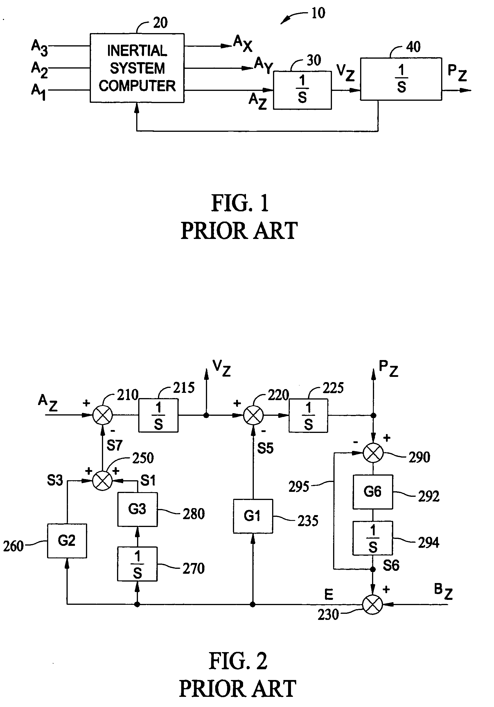
[0015]FIG. 1 is a simplified block diagram of a inertial navigation control system 10 which includes the above described orthogonal triad of accelerometers having outputs A1, A2 and A3 applied as inputs to an inertial navigation system computer 20. The accelerometers are orthogonally positioned relative to one another in order to provide orthogonal components of acceleration. After initialization of inertial navigation system computer 20, computer 20 is configured to calculate the orthogonal components of acceleration AX, AYy and AZ, where the acceleration AZ, is identified as the acceleration in the vertical direction, i.e., perpendicular to the earth's surface. The vertical acceleration information is further provided to an integrator 30, which determines a vertical velocity VZ, from the received vertical acceleration, AZ. Because gravitation and the earth's radius are included in the calculations performed by inertial system computer 20, vertical position information from a secon...


PUM


Abstract

An inertial navigation system which includes a first control system and a second control system is described. The first control system is configured to estimate a vertical velocity based in part on received vertical acceleration data. The second control system is configured to receive the estimated vertical velocity from the first control system and determine a compensated vertical velocity utilizing the estimated vertical velocity and airspeed.

Description

STATEMENT REGARDING FEDERALLY SPONSORED RESEARCH & DEVELOPMENT [0001] The United States Government has acquired certain rights in this invention pursuant to Contract No. N00019-02-C-3002 issued by the Department of the Navy.BACKGROUND OF THE INVENTION [0002] This invention relates generally to an inertial navigation system (INS), and more specifically, to methods and systems which utilize a true airspeed to improve the vertical accuracy of an INS. [0003] An inertial navigation system (INS), for example, an INS within an aircraft, provides a pilot and other systems within the aircraft with positional data. At least one known INS includes a vertical channel, which provides both a vertical velocity and a vertical position along a vertical axis. The vertical axis is defined as an axis that is perpendicular to the local level plane. Such an INS employs a triad of gyroscopes and accelerometers. These gyroscopes and accelerometers are mounted in an orthogonal manner with respect to one ano...

Claims


Application Information

Patent Timeline
Patent Type & Authority Applications(United States)
IPC IPC(8): G01C21/28
CPCG01C21/005G01C21/165
Inventor KIRKLAND, JEFFREY W.ANDERSON, JOHN F.
Owner HONEYWELL INT INC
Why Eureka
Try Eureka