
Information processing system in which information expressing a current time point is transmitted from one computer to another for use in calculating an amount of delay in transferring data between the computers

a technology of information processing system and current time point, which is applied in the field of information processing system, can solve the problems of large error in estimated values derived based on theoretical calculations, large range of detected values that are judged “abnormal” excessively wide, and achieve the effect of eliminating errors in calculation results

Inactive Publication Date: 2006-09-14
DENSO CORP
View PDF9 Cites 13 Cited by
  • Summary
  • Abstract
  • Description
  • Claims
  • Application Information

AI Technical Summary

Benefits of technology

The present invention provides an information processing system that allows two or more computers to communicate with each other and to directly measure the delay in transferring data between them. This is achieved by providing each computer with a timer counter that measures the current time point and a mechanism for transmitting information expressing the first and second time points between the computers. The first computer transmits the first time point information to the second computer at regular intervals, and the second computer calculates the difference between the two time points to determine the data communication delay. This system eliminates errors in the calculated delay by providing the actual delay value, rather than relying on theoretical calculations. Additionally, the system compensates for the effects of the data communication delay by using specific data sets that convey information other than the time point. This ensures accurate calculations even when the delay between the two computers is not known.

Problems solved by technology

For example there will be a certain amount of deviation between the time point at which a calculation is performed by the receiving microcomputer and the time point at which a (received) value used in that calculation was acquired by the transmitting microcomputer, resulting in an error in the calculation results.
However it is found in practice that there is a large amount of error in such estimated values that are derived based upon theoretical calculations.
If compensation is applied for the data communication delay based upon theoretical calculations performed beforehand, then due to the excessive amount of possible error, it is necessary to make the range of detected values that are judged “abnormal” excessively wide.
Hence, the use of such theoretically calculated values of data communication delay may have an adverse effect upon the overall operation of such an information processing system.

Method used


Image

  • Information processing system in which information expressing a current time point is transmitted from one computer to another for use in calculating an amount of delay in transferring data between the computers
  • Information processing system in which information expressing a current time point is transmitted from one computer to another for use in calculating an amount of delay in transferring data between the computers
  • Information processing system in which information expressing a current time point is transmitted from one computer to another for use in calculating an amount of delay in transferring data between the computers

Examples


Embodiment Construction

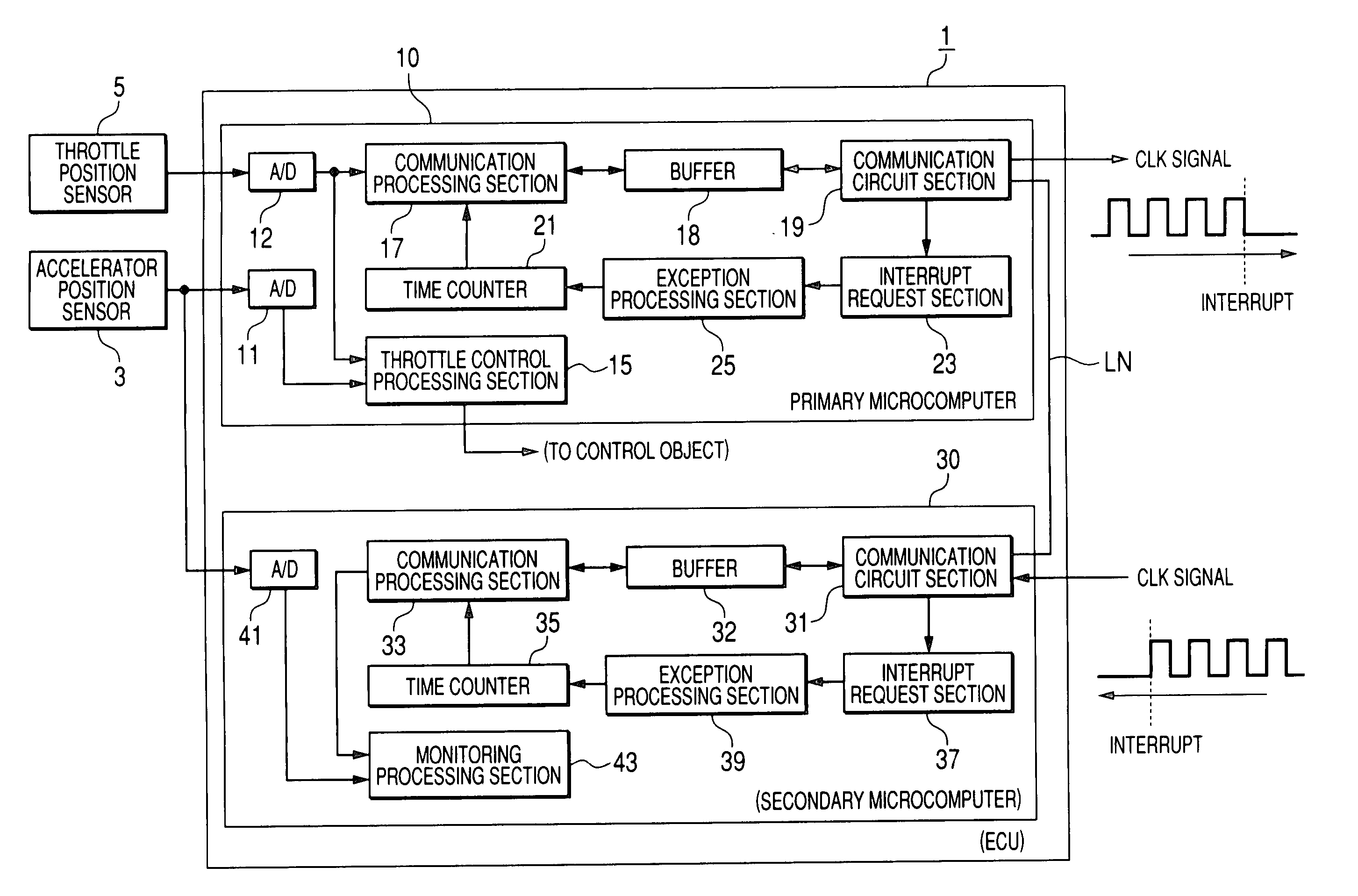
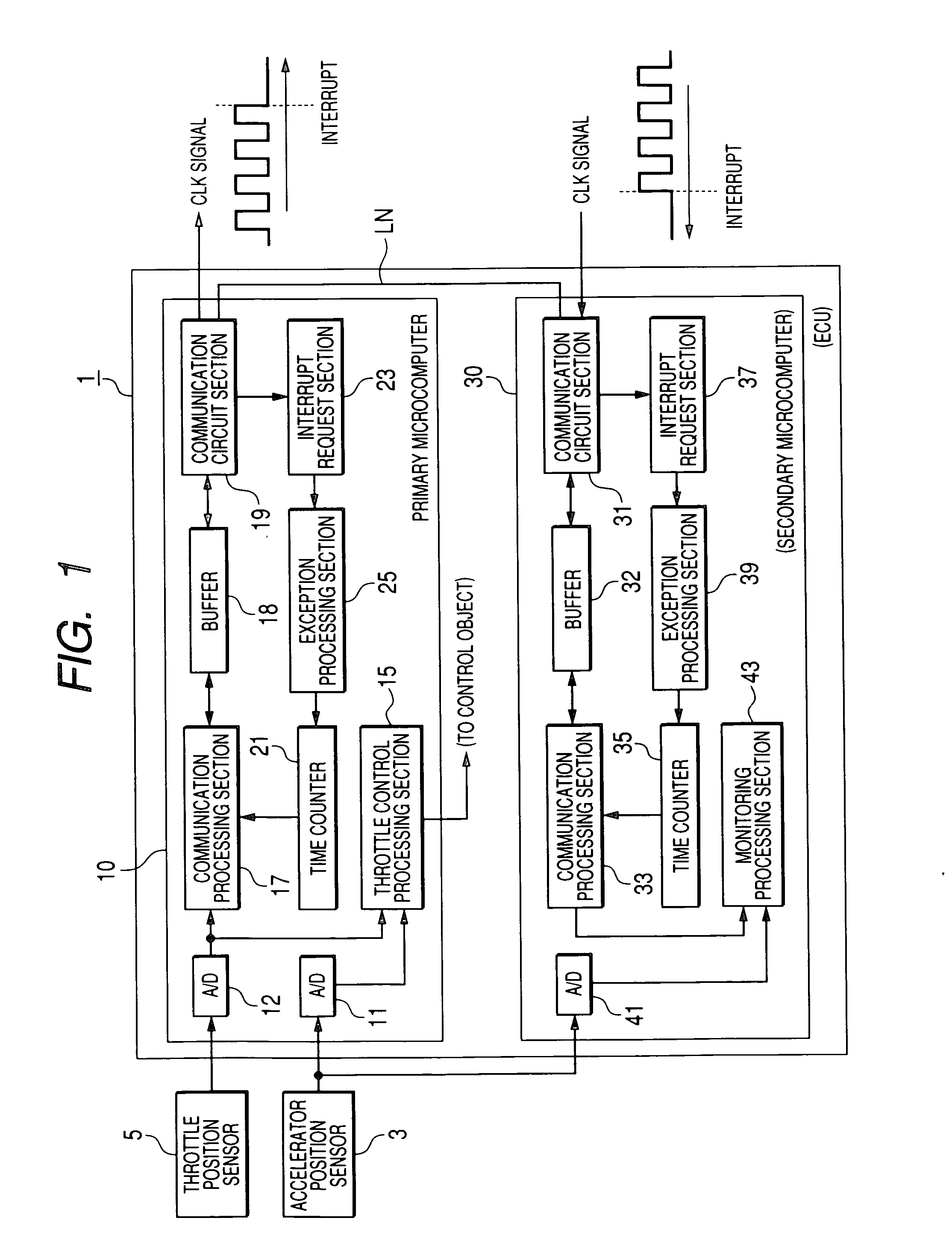
[0042]FIG. 1 is a general system block diagram of an embodiment of an electronic control unit (hereinafter abbreviated to ECU), designated by reference numeral 1, for use in a motor vehicle. The function of the ECU 1 is to control the throttle of the vehicle in which it is installed, in response to actuation of the accelerator pedal of the vehicle by the driver. The ECU 1 is connected to receive an (analog) sensor signal generated by an accelerator position sensor 3, which detects the extent to which the accelerator pedal is currently actuated, with that extent being referred to in the following as the accelerator actuation amount. The ECU 1 is also connected to receive an (analog) sensor signal generated by a throttle position sensor 5, which detects the extent to which the throttle of the vehicle is currently opened, with that extent being referred to in the following as the throttle opening amount.

[0043] The ECU 1 includes a primary microcomputer 10, which controls the throttle ...


PUM


Abstract

In a system in which a first computer transmits data to a second computer, the first computer transmits data conveying time information to the second computer, with the information expressing a first time point that occurs prior to commencement of the transmission and, following reception of the time information, the second computer compares the first time point information with a current time point, to thereby obtain a communication delay amount that includes a delay in transmitting data from the first to the second computer.

Description

CROSS-REFERENCE TO RELATED APPLICATIONS [0001] This application is based on and incorporates herein by reference Japanese Patent Application No. 2005-065437 filed on Mar. 9, 2005. BACKGROUND OF THE INVENTION [0002] 1. Field of Application [0003] The present invention relates to an information processing system having a plurality of computers which perform mutual data communication, such as a plurality of microcomputers of an ECU (Electronic Control Unit). [0004] In particular, the invention relates to such an information processing system, in which one computer performs calculation processing based on values that are transmitted from another of the computers [0005] 2. Description of Related Art [0006] Types of information processing system are known such as an ECU for controlling equipment of a motor vehicle (e.g., as described in Japanese patent publication No. 2003-138980), made up of a plurality of microcomputers which mutually exchange data. With such an ECU for example, one of ...

Claims


Application Information

Patent Timeline
Patent Type & Authority Applications(United States)
IPC IPC(8): G06F15/16
CPCB60W2050/065F16H59/18H04L69/28
Inventor NARITA, NOBUAKI
Owner DENSO CORP
Learn More