Substrate-placing mechanism having substrate-heating function

a substrate and heat dissipation mechanism technology, applied in the direction of drying machines, drying, light and heating apparatus, etc., can solve the problems of feed rod thermal expansion, feed wire breaking or the like, etc., to increase the transverse rigidity, and increase the horizontal rigidity

Active Publication Date: 2006-09-21
TOKYO ELECTRON LTD
View PDF3 Cites 4 Cited by
  • Summary
  • Abstract
  • Description
  • Claims
  • Application Information

AI Technical Summary

Benefits of technology

[0013] In addition, for example, the feed member comprises a feed rod and a feed wire of a braided structure. In addition, for example, the spring member is a plate spring. Herein, it is preferable that the plate spring mainly consists of one or more horizontal-plane parts and one or more vertical-plane parts. In such a case, it is easy to design a plate spring having an increased transverse rigidity. The plate spring having an increased transverse rigidity doesn't resonate when some vibration is generated. That is, the plate spring having an increased horizontal rigidity doesn't have any bad effect on the feed member.

Problems solved by technology

If the size of the substrate-processing apparatus is large, it is impossible to ignore thermal expansion of the feed rod when the semiconductor wafer is heated by the ceramic heater.
That is, breaking or the like at a feed member such as a feed wire may be caused by repetition of heating.

Method used


Image

  • Substrate-placing mechanism having substrate-heating function
  • Substrate-placing mechanism having substrate-heating function
  • Substrate-placing mechanism having substrate-heating function

Examples


first embodiment

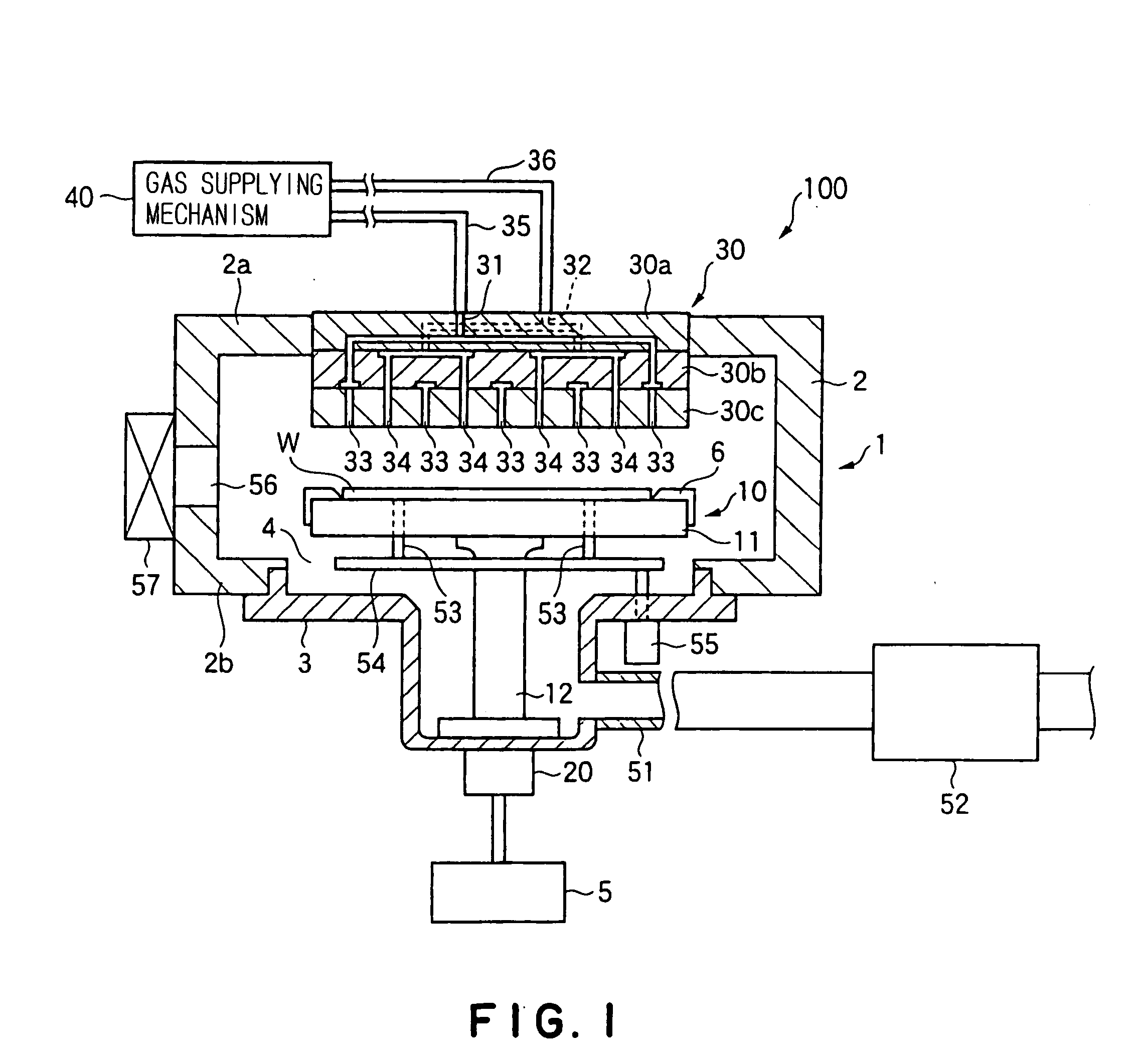
[0025]FIG. 1 is a schematic sectional view showing a CVD film-forming apparatus including a wafer-placing mechanism according to the present invention. The CVD film-forming apparatus 100 has a processing container 1. The processing container 1 has a hermetically sealed chamber 2 of a substantially cylindrical shape, and a gas-discharging chamber 3 protruded downwardly from a bottom wall 2b of the chamber 2. In the chamber 2, a wafer-placing mechanism 10 for placing thereon a semiconductor wafer W, as an object to be processed, in a horizontal position is provided. The wafer-placing mechanism 10 has a wafer-placing stage 11 having a wafer-placing surface, and a cylindrical supporting member 12 that stands up at a base portion of the processing container 1 and supports a central portion of the wafer-placing stage 11. In addition, as described below, the wafer-placing mechanism 10 has a heat-generating body buried in the wafer-placing stage 11, and a feed mechanism for feeding electric...

second embodiment

[0042] Next, a wafer-placing mechanism according to the present invention is explained.

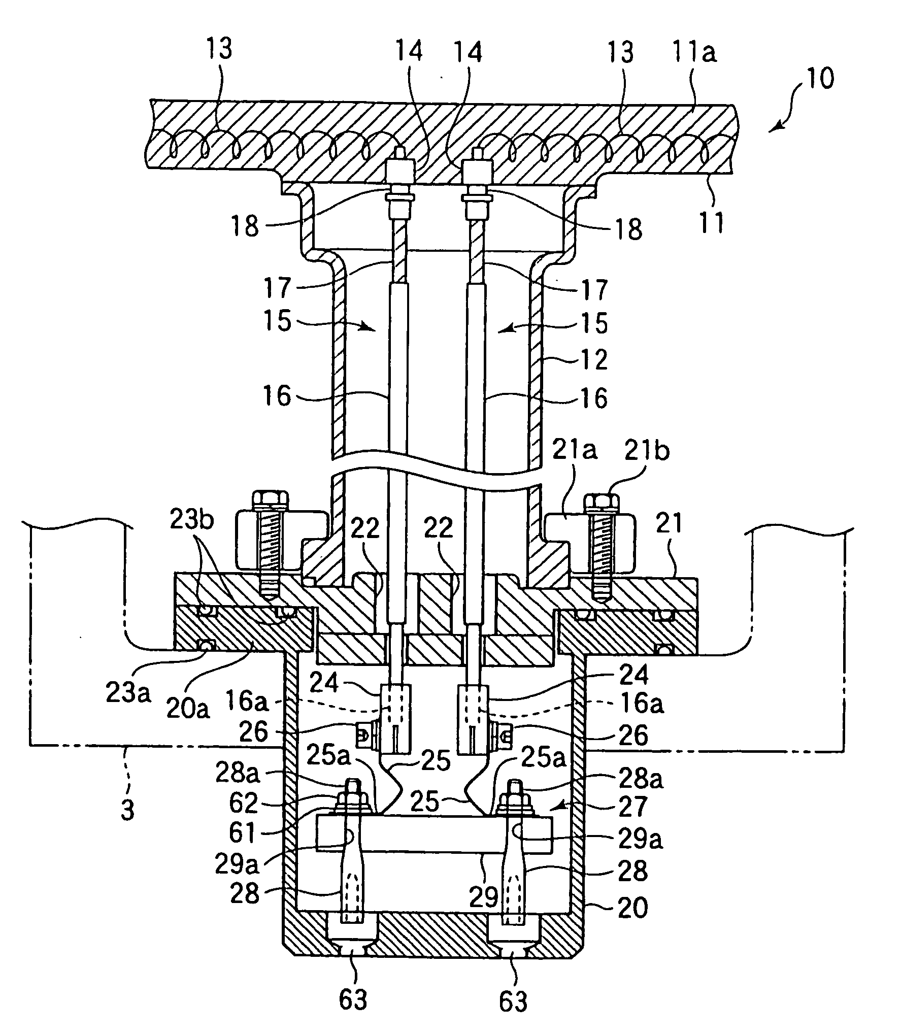
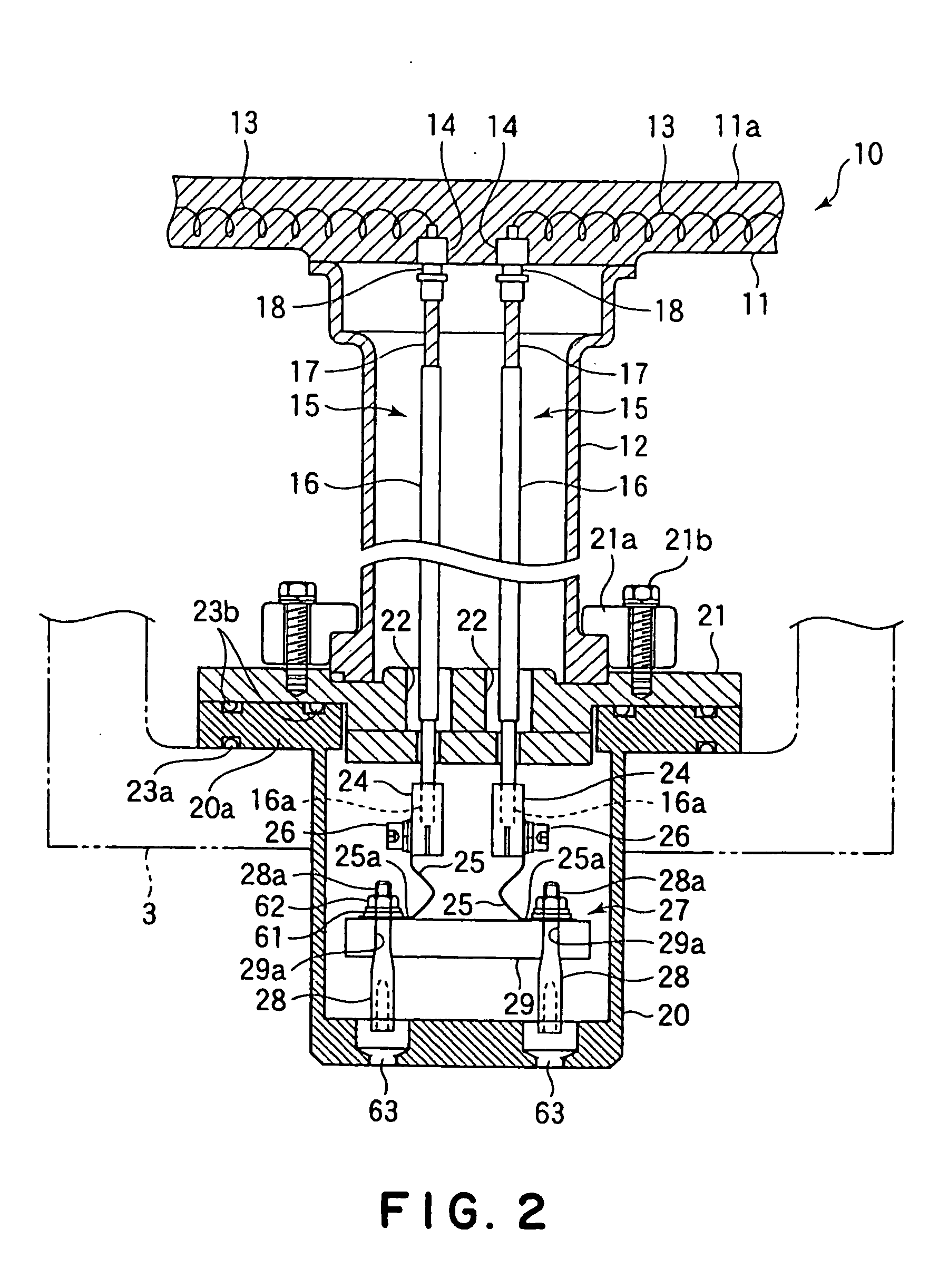
[0043] In the above first embodiment, the thermal expansion of the feed rods 16, which take the majority of the feed members 15, can be mainly absorbed by the plate springs 25. However, when the whole thermal expansion is not absorbed by the plate springs 25, a redundant part of the thermal expansion is absorbed by bending of the feed wires 17 consisting of the braided conductors. In the case, each feed wire 17 that has been subjected to a tensile force by a weight of each corresponding feed rod 16 at a room temperature is subjected to a compressive force by thermal expansion of the feed rod 16, so that a buckling may be caused at the feed wire 17. When such a heating process is repeated, the buckling may be caused at the feed wire 17 repeatedly. Then, a complex stress is caused in the feed wire 17, and the periphery is at a high temperature, so that a creep is likely to be generated at the feed w...


PUM


Abstract

The present invention is a substrate-placing mechanism to be provided in a processing container of a substrate-processing apparatus including: a stage having: a base body on which a substrate is placed, a heat-generating body for heating the substrate placed on the base body, and a feed terminal part for feeding electric power to the heat-generating body; a hollow supporting part fixed to a base of the processing container for supporting the stage; a connection terminal part fixed to the base of the processing container under the supporting part for being connected to an electric power source located outside the processing container; a feed member connected to the feed terminal part and extending in the hollow supporting part; and a spring member that connects the feed member and the connection terminal part.

Description

FIELD OF THE INVENTION [0001] This invention relates to a substrate-placing mechanism having a substrate-heating function, which heats a substrate such as a semiconductor wafer placed thereon in a processing container, and to a substrate-processing apparatus including the substrate-placing mechanism.BACKGROUND ART [0002] In order to manufacture a desired semiconductor device, various vacuum processes including a CVD film-forming process and / or a plasma etching process are carried out to a substrate to be processed, for example a semiconductor wafer. In such a process, the semiconductor wafer has to be heated to a predetermined temperature. Thus, a heater is used to heat a substrate-supporting member. [0003] As such a heater, a stainless-steel heater or the like is used conventionally. However, recently, a ceramic heater has been spread because it has high corrosion resistance against a halogen gas used in the process and high thermal efficiency. The ceramic heater has a base body se...

Claims


Application Information

Patent Timeline
Patent Type & Authority Applications(United States)
IPC IPC(8): F26B21/06F26B5/04
CPCH01L21/67103H01L21/324
Inventor KOMATSU, TOMOHITO
Owner TOKYO ELECTRON LTD
Why Eureka
Try Eureka