Apparatus and method for controlling elastic actuator

a technology of elastic actuators and actuators, applied in the direction of electric controllers, programme control, servomotors, etc., can solve the problems of difficult control of elastic actuators, high rigidity and poor flexibility of electric motors, and inability to adapt to domestic use of electric motors used in conventional industrial robots. , to achieve the effect of low dynamic influence, good responsivity and high accuracy

Active Publication Date: 2006-09-21
PANASONIC CORP
View PDF6 Cites 79 Cited by
  • Summary
  • Abstract
  • Description
  • Claims
  • Application Information

AI Technical Summary

Benefits of technology

[0040] With the control apparatus according to the present invention, the internal state error compensation means is arranged to form the control system in which the elastic actuator internal state changed by the driving of the elastic actuator is fed back, and the desired internal state determination means is arranged to form the control system in which the feedforward of the desired internal state is performed. Therefore, the high-speed, high-accuracy control can be performed with good responsivity and low steady-state deviation.
[0099] With the control method according to the nineteenth aspect of the present invention, the driving force feedback control system in which the driving force generated by the elastic actuator is fed back is configured while the driving force error compensation operation is performed, the internal state feedback control system in which the elastic actuator internal state changed by the driving of the elastic actuator is fed back is configured independently of the driving force feedback control system while the internal state error compensation operation is performed, and the feedforward of the desired internal state is performed while the desired internal state determination operation is performed. Therefore, the elastic actuator drive-type movable mechanism can accurately be controlled with good responsivity, low dynamic influence, low steady-state deviation, and high accuracy.

Problems solved by technology

However, because a mechanism driven by the electric motor often has high rigidity and poor flexibility, there are many issues from a safety standpoint.
Accordingly, the electric-motor driven mechanism used in the conventional industrial robot is not suitable to the domestic-robot field in which the safety is emphasized, and the flexible and safe robot arm is required.
However, the hydropneumatic drive actuator such as the McKibben type actuator, which is operated by the fluid pressure such as air, has an issue that generally the elastic actuator is difficult to control, for example, in the elastic actuator, the responsivity is worsened due to the elastic property generated by the fluid compressibility, the influence of the channel resistance etc., and the like.
However, in the above control apparatus including the delay circuit, since the delay is always generated for a desired operation, responsivity is worsened and the work necessary to be processed in real time cannot be performed.

Method used


Image

  • Apparatus and method for controlling elastic actuator
  • Apparatus and method for controlling elastic actuator
  • Apparatus and method for controlling elastic actuator

Examples


first embodiment

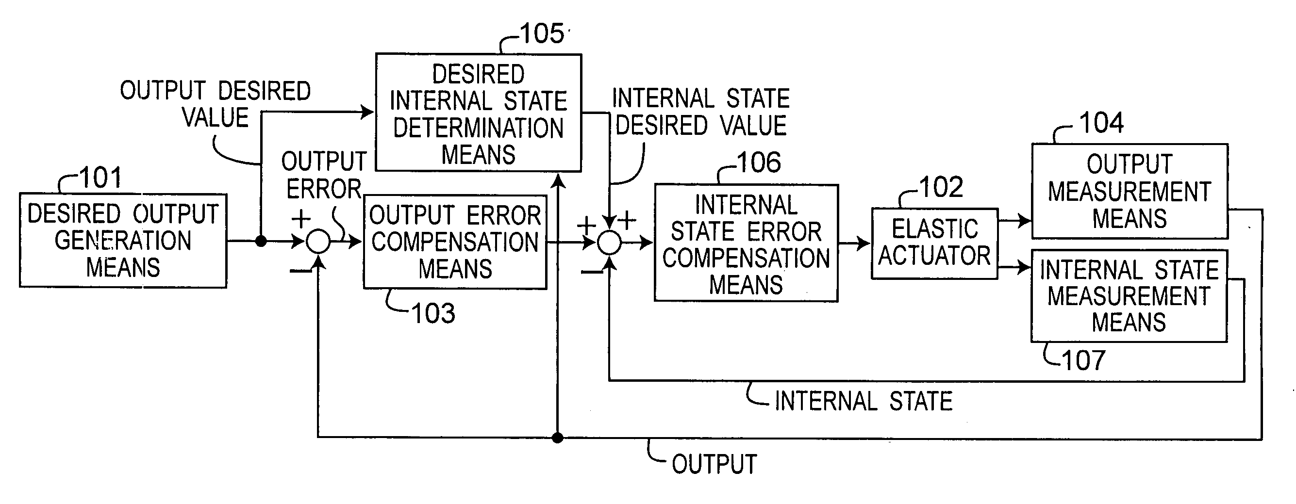
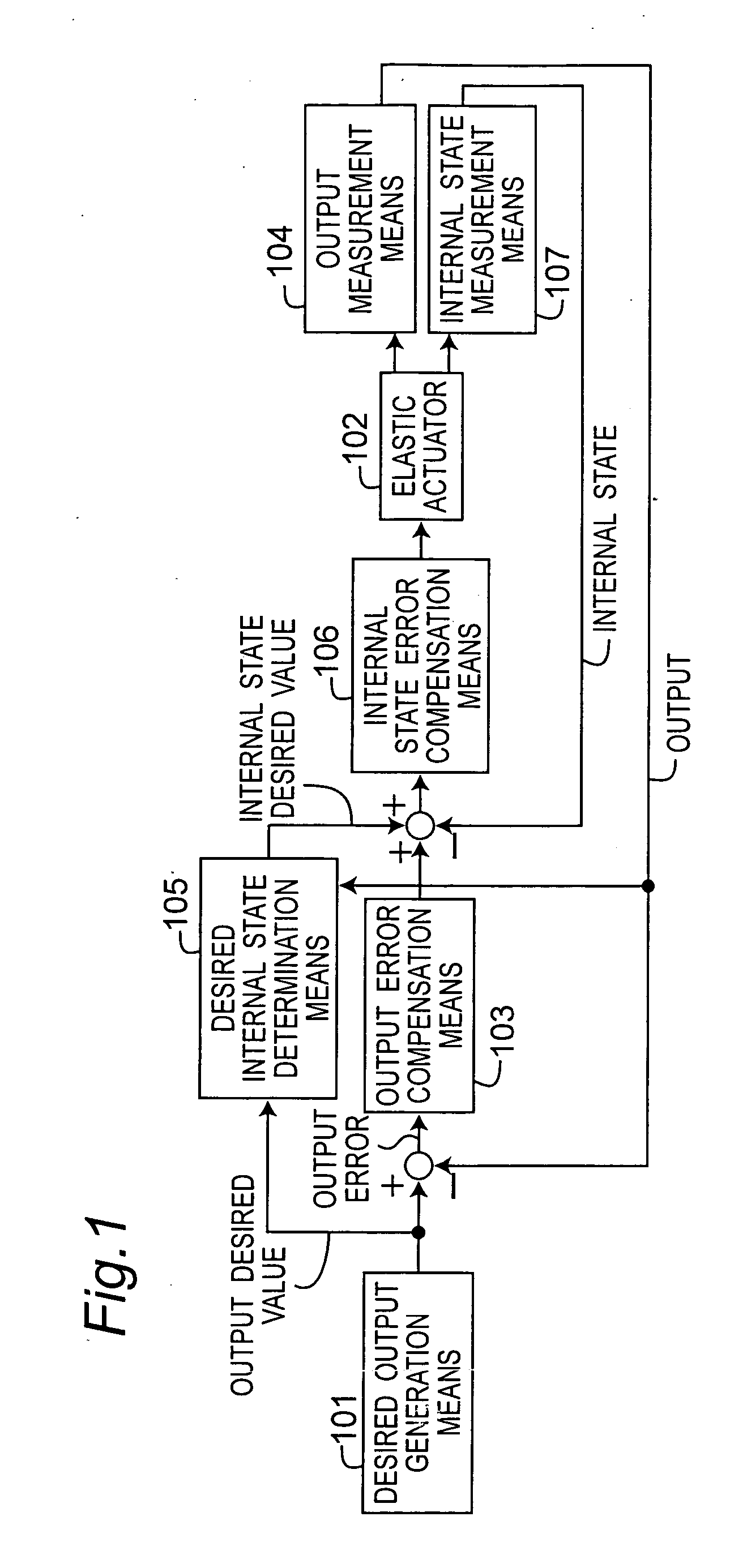
[0238]FIG. 1 is a block diagram showing a concept of an elastic actuator control apparatus according to a first embodiment of the present invention. In FIG. 1, the reference numeral 101 designates a desired output generation means for generating an output desired value of an elastic actuator 102 which is a hydropneumatic drive actuator driven by fluid pressure. The reference numeral 104 designates an output measurement means connected to the elastic actuator 102. The output measurement means 104 measures the output measurement value of the elastic actuator 102 to input the measurement value to a desired internal state determination means 105 and an output error compensation means 103, respectively. The reference numeral 103 designates the output error compensation means to which the desired value is inputted from the desired output generation means 101. The output error compensation means 103 performs control such that the output measurement value of the elastic actuator 102 measure...

second embodiment

[0289]FIG. 10 is a view showing a configuration of an elastic actuator control apparatus according to a second embodiment of the present invention. In FIG. 10, the reference numeral 201 designates a gravity compensation means. In a control system shown in FIG. 10, the desired track generation means 11 outputs the desired joint angle vector qd of the robot arm 10, and the joint angle feedback control is performed to compensate the difference qd with the current joint angle vector q measured by the encoder 8. Other configurations are similar to those of the control apparatus of the first embodiment shown in FIG. 6, so that the description will be omitted.

[0290] The current joint angle vector q measured by the encoder 9 is inputted to the gravity compensation means 201, and the gravity compensation means 201 calculates the orientation of each link of the robot arm 10 and, also, calculates a torque value which is generated in each joint axis by the influence of the gravity. The torque ...

third embodiment

[0292]FIG. 11 is a view showing a configuration of an elastic actuator control apparatus according to a third embodiment of the present invention. In FIG. 11, the reference numeral 202 designates a temperature compensation means. A temperature sensor (not shown) which is an example of the internal state measurement means 107 is arranged in the robot arm 10, and measures a temperature T of the elastic body of the elastic actuator 102. Other configurations are similar to those of the control apparatus of the second embodiment shown in FIG. 10, so that the description will be omitted.

[0293] When the elastic body temperature of the elastic actuator 102 is changed, an elastic modulus of the elastic body is changed to change the coefficients A and b of the equation (1) for calculating the desired pressure difference ΔPd. The temperature T is inputted to the temperature compensation means 202 in order to compensate the influence of the temperature change of the elastic body. The temperatu...


PUM

PropertyMeasurementUnit
degrees of freedomaaaaaaaaaa

Abstract

An internal pressure of a hydropneumatic drive actuator is measured by a pressure measurement device, a displacement amount of a movable mechanism is measured, a desired value and a measurement value of the displacement are inputted so that a position error is compensated by a position error compensation device, a desired value of a pressure difference of the actuator to which antagonistic driving is performed by the desired value is calculated by a desired pressure difference calculation device, outputs from the position error compensation device, the desired pressure difference calculation device, and the pressure measurement device are inputted, and a pressure difference error is compensated by pressure difference error compensation device.

Description

[0001] This is a continuation application of International Application No. PCT / JP2004 / 013788, filed Sep. 22, 2004.BACKGROUND OF THE INVENTION [0002] The present invention relates to elastic actuator control apparatus and method that control the operation of an elastic actuator such as a hydropneumatic drive actuator driven by deformation of an elastic body. The present invention also relates to elastic actuator drive-type movable mechanism control apparatus and method that control a movable mechanism driven by the elastic actuator. [0003] Recently, domestic robots such as a pet robot are actively developed, and practical realization of the practical domestic robots such as a household assistance robot is expected in the future. Because it is necessary that the domestic robot go in a home to live with a human, the domestic robot differs from the conventional, industrial robot and the like in the required specifications. [0004] In the industrial robot, an electric motor and a speed re...

Claims


Application Information

Patent Timeline
Patent Type & Authority Applications(United States)
IPC IPC(8): F15B21/02B25J9/14F15B9/09F15B11/20F15B15/10
CPCB25J9/142F15B9/09F15B11/20F15B15/103
Inventor OKAZAKI, YASUNAOYAMAMOTO, MASAKIADACHI, YUJIASAI, KATSUHIKO
Owner PANASONIC CORP
Why Eureka
Try Eureka