
Method and device for controlling an internal combustion engine

a technology of internal combustion engine and control device, which is applied in the direction of electric control, fuel injection apparatus, charge feed system, etc., can solve the problems of inability to design and operate faster controllers, smoke emissions occur when such devices are used, etc., to achieve accurate measurement of injected fuel quantity, increase emissions, and easy addition or multiplication

Inactive Publication Date: 2006-09-21
ROBERT BOSCH GMBH
View PDF4 Cites 3 Cited by
  • Summary
  • Abstract
  • Description
  • Claims
  • Application Information

AI Technical Summary

Benefits of technology

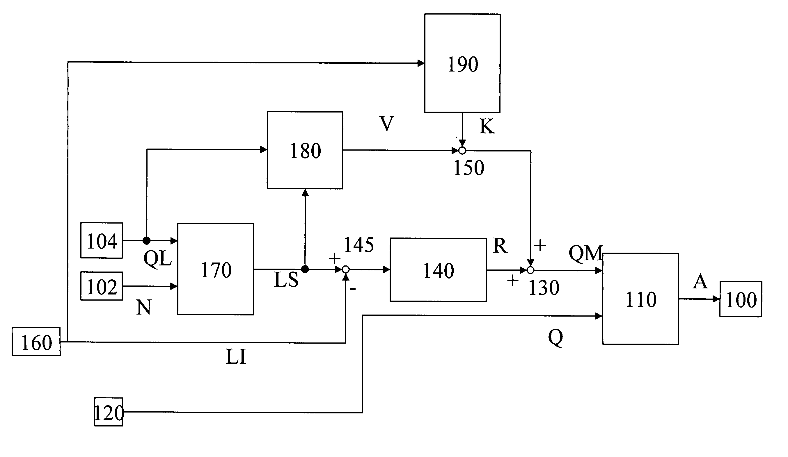
[0004] The controller ascertains the output signal on the basis of a comparison between an expected lambda value and an actual lambda value. The lambda values are a very accurate measure of the injected fuel quantity. If the fuel quantity differs from the desired value in such a way that increased emissions possibly occur, this can be recognized even in the case of minor deviations. The use of the closed-loop controller allows the limiting value to be very accurately ascertained.
[0005] It is advantageous in particular if the correction value is additively and / or multiplicatively superimposed on the precontrol value. The correction value is easily added to or multiplied by the precontrol value, requiring little resources in the control unit. The correction is especially flexible when both additive and multiplicative correction values are ascertained and used.

Problems solved by technology

In particular, during acceleration or when starting off, smoke emissions occur when such a device is used.
The controller cannot be designed to act faster due to the gas transport time and the associated inertia in the control loop.

Method used


Image

  • Method and device for controlling an internal combustion engine
  • Method and device for controlling an internal combustion engine
  • Method and device for controlling an internal combustion engine

Examples


second embodiment

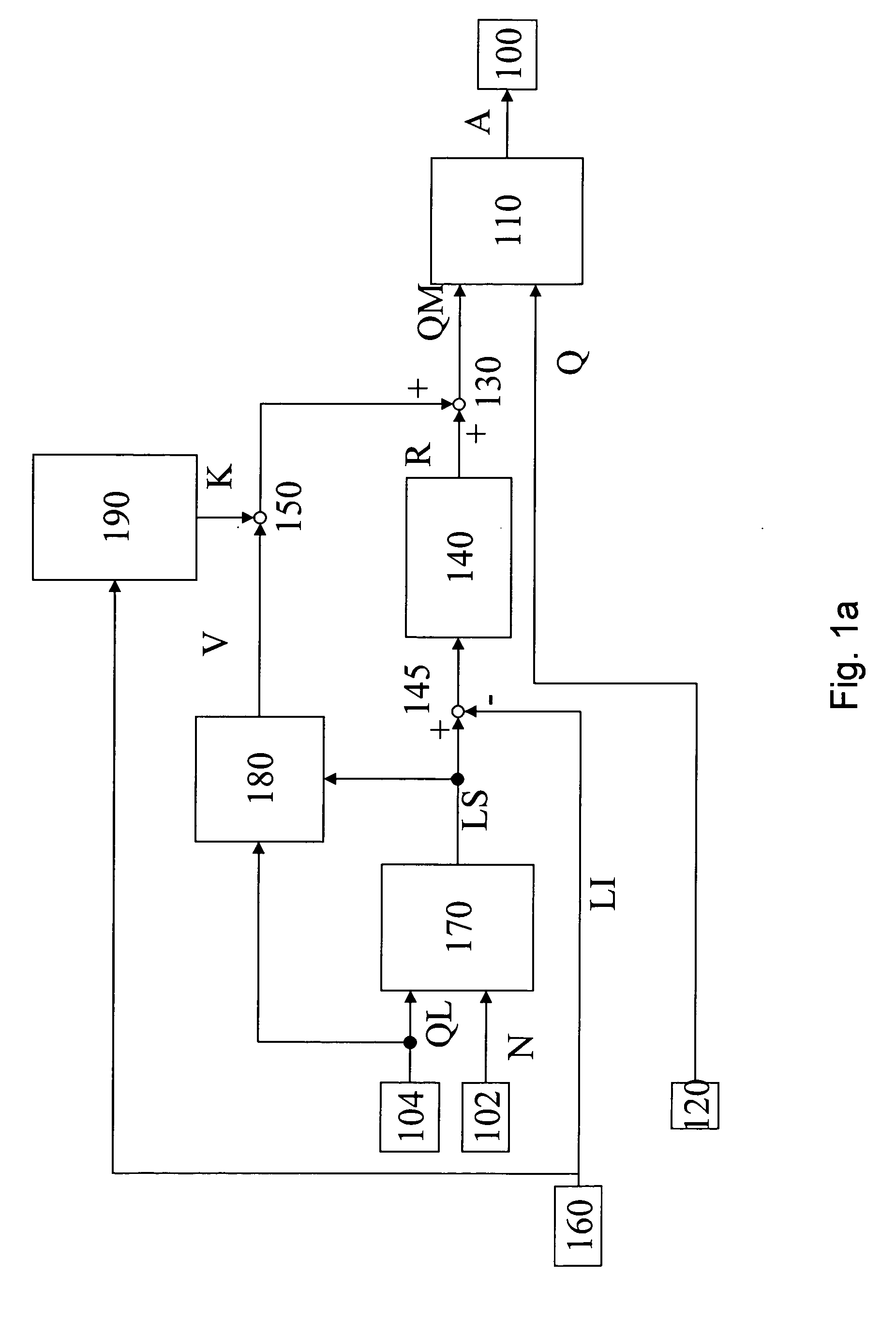
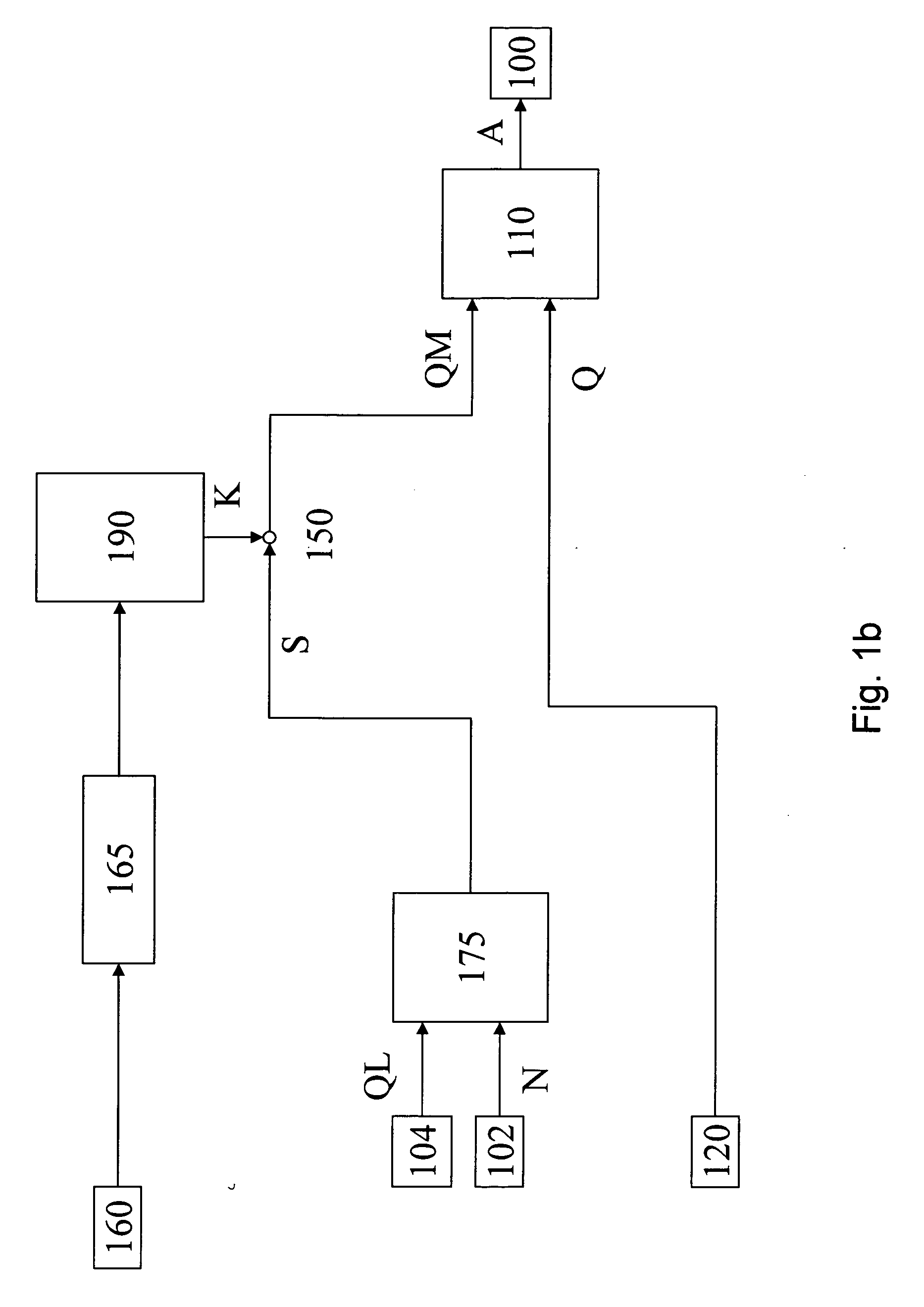
[0017] According to the present invention, precontrol value V is corrected in node 150 with the aid of a correction value K, which is provided by correction value predefining element 190. In a simple embodiment, additive gating is performed in the node. This means that correction value K is added to precontrol value V. In a second embodiment, the correction value is provided as a multiplicative factor by which precontrol value V is multiplied. An additive and a multiplicative correction may also be performed. This means that correction value predefining element 190 determines and saves the correction value in the presence of certain operating states in which this is possible. The correction value may then be used for the correction in all operating states. Correction is therefore possible even in operating states in which it is impossible to determine a correction value.

[0018] Dynamic advantages, i.e., lower exhaust gas emissions during acceleration, occur thanks to this procedure, ...

first embodiment

[0021] In the following a first embodiment for ascertaining correction value K is described using the example of a correction factor. The procedure is not limited to a correction factor using which multiplicative correction is performed in node 150. A similar procedure may also be used in the case of an additive correction value. Minimum values of desired lambda value LS and actual lambda value Li are ascertained during a full-load acceleration. When minimum actual value LIM is less than minimum setpoint value LSM, the engine is being operated with an excessively rich mixture. In this case, limiting value QM for future full-load accelerations is corrected by correction factor K to smaller values. A correction factor of less than one is preferably used, and the precontrol value is multiplied by this value in node 150. For reasons of statistical relevance and driving comfort, the deviation is not compensated from one full-load acceleration to the next, but only gradually.

[0022] The fo...


PUM


Abstract

A method and device for controlling an internal combustion engine, in which the fuel quantity to be injected into the engine is limited to a limiting value. The limiting value is predefined on the basis of the output signal of a closed-loop controller or an open-loop controller and a precontrol value. Furthermore, the precontrol value is corrected.

Description

BACKGROUND INFORMATION [0001] German Patent No. DE 103 16 185, for example, describes a method and a device for controlling an internal combustion engine, in which the fuel quantity to be injected into the engine is limited to a limiting value. In that document, a closed-loop controller emits a controller output signal on the basis of the deviation between a setpoint value and an actual value of a lambda signal. An open-loop controller predefines a precontrol value for the limiting value on the basis of performance characteristics, the precontrol value being gated with the closed-loop controller output signal for forming the limiting value. Alternatively, an open-loop controller may be used instead of a closed-loop controller. SUMMARY OF THE INVENTION [0002] In particular, during acceleration or when starting off, smoke emissions occur when such a device is used. It has been recognized according to the present invention that these smoke emissions are due to the fact that the injecto...

Claims


Application Information

Patent Timeline
IPC IPC(8): F02D41/14
CPCF02D41/10F02D41/1402F02D41/1454F02D41/187F02D41/38F02D2041/141F02D2250/26F02D2250/32F02D2250/38
Inventor MICHALSKE, ANDREASAUTH, SASCHA-JUAN MORAN
Owner ROBERT BOSCH GMBH
Learn More