Precision substrate storage container

a technology of substrate storage and storage container, applied in the direction of photomechanical treatment originals, packaging goods types, instruments, etc., can solve the problems of affecting the performance of information transmission, affecting the accuracy of information transmission, so as to prevent communication failure and reduce information transmission function, and achieve no variation in information transmission ability.

Active Publication Date: 2006-09-21
SHIN-ETSU POLYMER CO LTD
View PDF10 Cites 24 Cited by
  • Summary
  • Abstract
  • Description
  • Claims
  • Application Information

AI Technical Summary

Benefits of technology

[0014] The present invention has been devised in view of the above, it is therefore an object to provide a precision substrate storage container which is able to prevent communication failure and lowering of information transmission function by permitting its non-contact type information medium to change its directivity in multiple directions, and which brings no variation into information transmission ability even if it is used at different sites, with different equipment units or in other ways.

Problems solved by technology

In the prior art, the type of semiconductor wafers and the information as to the precision substrate storage container etc., are discriminated and identified in the above ways, however, these techniques entail the following problems.
First, in ether case of the above patent literatures, since the transponder is oriented to one direction only, communication failure is liable to take place even if an identical transponder is used, depending on the setup specification of the communication area on the equipment side; this is a big problem.
Generally, a typical transponder is given in a cylindrical form, which is prone to induce setting in a wrong direction.
Wrong directivity degrades information transfer performance and may cause difference in information transmission function during use even if transponders and precision substrate storage containers of the same kinds are used.
Meanwhile, system configurations have not been unified in different plants handling precision substrate storage containers while the position and direction for transmitting and receiving transmission signals are diverse between different equipment units.
As a result, if a precision substrate storage container with RFID, which has functioned correctly at a certain plant, is attempted to be used in another plant or another process, there is more than a little possibility of information exchange becoming difficult or impossible.
Further, since the usable frequency for the reading / writing area is different depending on the country, if a precision substrate storage container is used abroad, the precision substrate storage container should be configured so as to be usable inside and outside the country, or it is necessary to severely manage and discriminate the products for domestic use and overseas use.
Furthermore, though the transponder of the system is communicable even if it is more or less deviated from the front of the interrogator, the reading area becomes smaller by 20 to 30% as its relative position to the interrogator changes 90 degrees, therefore there is a fear of communication errors occurring due to its position relative to the interrogator.
However, if the reading area is enlarged so as to solve the above problem, there occurs a new problem in that the contents from other adjacent transponders residing nearby may be erroneously picked up.

Method used


Image

  • Precision substrate storage container
  • Precision substrate storage container
  • Precision substrate storage container

Examples


second embodiment

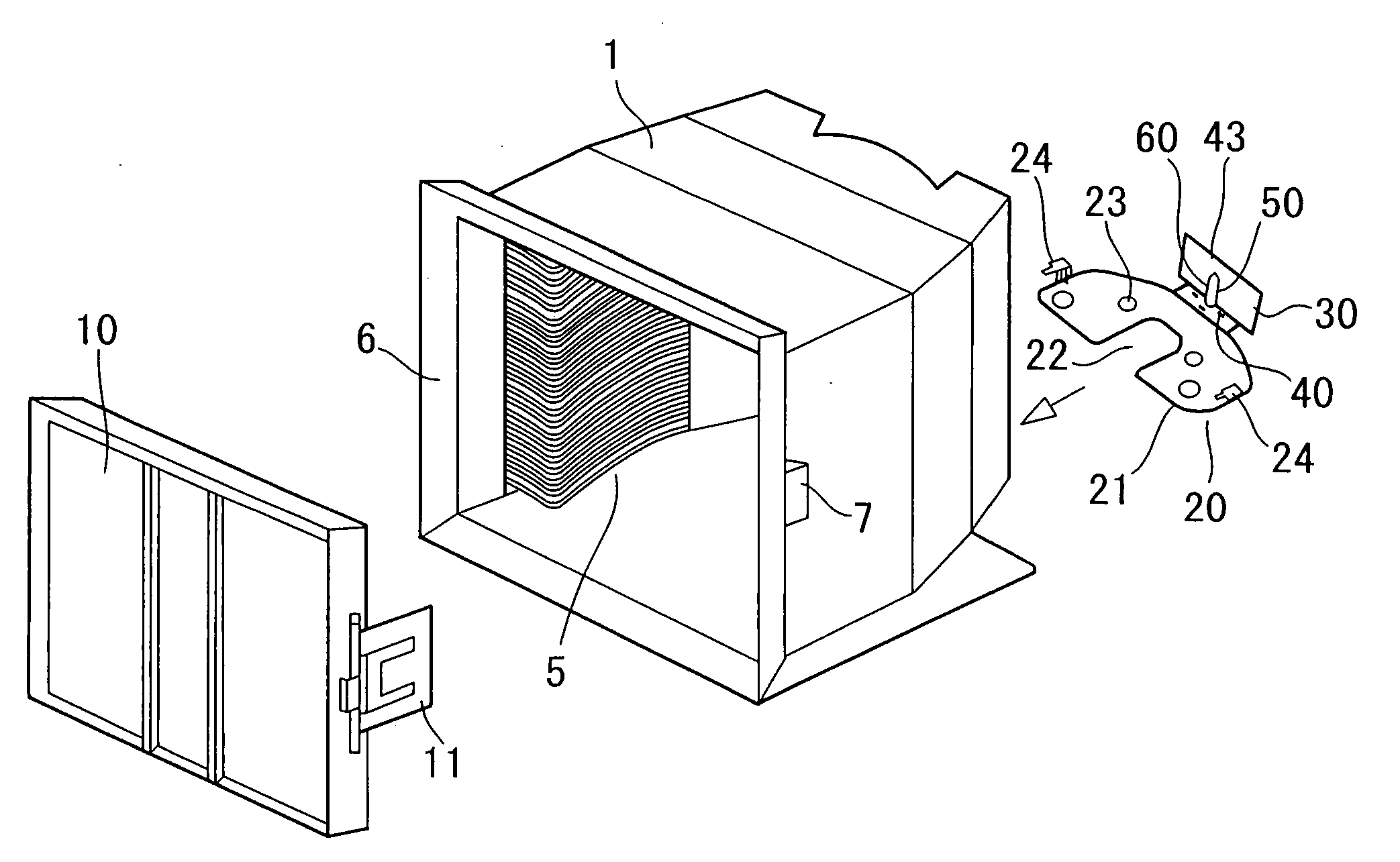
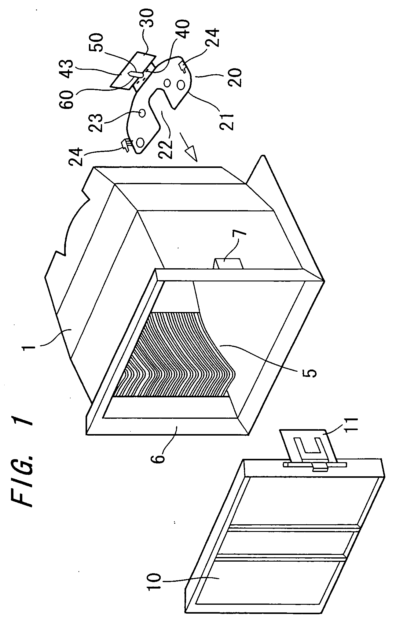
[0075] Next, FIGS. 11 and 12 show the present invention. In this case, a bottom plate 20 is constituted of a base plate 21 opposing the bottom of container body 1 and a wall plate 30 erected on base plate 21. A first supporting structure 40 for directly or indirectly supporting a transponder 60 which is positioned approximately horizontally is provided on base plate 21 while a second supporting structure 43 for directly or indirectly supporting transponder 60 which is positioned approximately vertically is provided on the inner face of wall of wall plate 30.

[0076] First and second supporting structures 40 and 43 may be configured to directly hold transponder 60 or may hold it indirectly by means of a holder 50. Also, engaging claws 41 and 41A or engaging ribs 42 and 42A may be provided so as to hold transponder 60 directly or indirectly. Alternatively, with omission of these, projections or other structures that engage flanges 52 of holder 50 or draining holes 51 of holder 50 may be...

third embodiment

[0078] Next, FIG. 13 shows the present invention. In this case, at least one of first and second supporting structures 40 and 43 is composed of multiple engaging claws 41A that define a rectangle with its transverse length greater than the width of a holder 50 and a pair of engaging ribs 42A located at the middle points of the long sides of the rectangle defined by these multiple engaging claws 41A, so that the position of holder 50 holding a transponder 60 can be selectively changed so as to take one of three directions.

[0079] The present embodiment will be illustrated taking an example of second supporting structure 43. Multiple engaging claws 41A are arranged on the front face of wall plate 30 at the four corners of the rectangle, each engaging claw 41A having a bent form of a transverse-long L-shape, and the engaging claws 41A function to engage the corners of holder 50. Paired engaging ribs 42A are arranged apart from each other on the front face of wall plate 30, each engaging...


PUM

PropertyMeasurementUnit
diameteraaaaaaaaaa
environment resistanceaaaaaaaaaa
frequencyaaaaaaaaaa

Abstract

The purpose is to provide a precision substrate storage container which is able to prevent communication failure and lowering of information transmission function by permitting its non-contact type information medium to change its directivity in multiple directions, and which brings no variation into information transmission ability even if it is used at different sites, with different equipment units or in other ways. The precision substrate storage container is comprised of: a bottom plate 20 removably attached to the bottom of a container body 1 in which a multiple number of semiconductor wafers are accommodated in alignment; a holder 50 removably supported on bottom plate 20; and a RFID system transponder 60 held in holder 50. Bottom plate 20 is composed of a base plate 21 opposing the rear bottom of container body 1 and a wall plate 30 erected on base plate 21. The base plate 21 is formed with a first supporting structure 40 for supporting holder 50 that is oriented in the horizontal direction and a second supporting structure 43 for supporting holder 50 that is oriented in the vertical direction so as to selectively change the position of holder 50 taking one of the two directions, longitudinal and transverse.

Description

TECHNICAL FIELD [0001] The present invention relates to a precision substrate storage container which is used for storage, preservation, transportation, conveyance and shipment of precision substrates such as semiconductor wafers, mask glass and the like, and which can be coupled to mechanical interface (SMIF), FIMS (Front-opening interface Mechanical Standard) system and the like, standardized for the precision substrate fabrication process. BACKGROUND ART [0002] Though unillustrated, a conventional precision substrate storage container is composed of a container body for storing multiple semiconductor wafers in alignment, a door component for opening and closing the container body and a bottom plate attached to the bottom surface of the container body. [0003] The container body has a front-open box configuration having an opening in the front and a multiple number of paired supporting ribs arranged vertically on the interior walls on both sides for supporting semiconductor wafers ...

Claims


Application Information

Patent Timeline
Patent Type & Authority Applications(United States)
IPC IPC(8): B65D85/00H01L21/673
CPCG03F1/66H01L21/67379H01L21/67294H01L21/02H01L21/68
Inventor MIMURA, HIROSHINIITA, WATARUKAMADA, TOSHIYUKI
Owner SHIN-ETSU POLYMER CO LTD
Why Eureka
Try Eureka