Luminescent calibration

a luminescent calibration and calibration method technology, applied in the field of calibration techniques, can solve the problems of changing the performance of biological samples, conventional calibration does not address the problems of day-to-day variation of optical systems or biologic samples, and cannot be done with sufficient accuracy. to achieve the effect of removing day-to-day variability

Inactive Publication Date: 2006-09-21
UVP ULTRA VIOLET PRODS
View PDF13 Cites 37 Cited by
  • Summary
  • Abstract
  • Description
  • Claims
  • Application Information

AI Technical Summary

Benefits of technology

[0012] It is another aspect of the invention, to remove day-to-day variability from the processing and interpretation of optical data.

Problems solved by technology

At present, conventional calibration of optical systems and their target samples can not be done with sufficient accuracy.
However, while this kind of calibration provides useful information as to sensitivity of the optical system, it does not provide calibration solutions to many different kinds of problems that would make the calibration of the optical system more useful and data sensitive relative to a biologic sample.
For instance, conventional calibration does not address problems of day-to-day variation of an optical system or variations in the biologic sample.
Additionally, environmental changes can also change the performance of the biological sample.
Thus, affecting the ability of being able to correlate or compare one set of data to another set of data.
Moreover, it should be noted that because of these day-to-day variations, the data that is collected has an inherent uncertainty and variation in it that may skew and affect the analysis of the collected data.
In yet another example of a problem, day-to-day degradation over time of the optical detection system and the light emitting system can not be taken into account with the present state of the art.
Additionally, comparison of an earlier data set to a later data can not be accurately achieved.
In both the light emitting system and the optical detection system, there are many causes of degradation such as, but not limited to, chemical and physical fatigue of the emitting source and detection system, diffusion of unwanted gases into the emitting chamber and the detection materials, and the like.
This leads to inaccurate data acquisition and interpretation of the collected data.
Moreover, comparing the data over time is extremely difficult, if not impossible, to do in some meaningful way.
It can be readily seen that conventional calibration techniques and optical systems have several disadvantages and problems.
These problems and disadvantages do not allow for sufficient precision and full utilization of all the data.

Method used


Image

  • Luminescent calibration
  • Luminescent calibration
  • Luminescent calibration

Examples


example 1

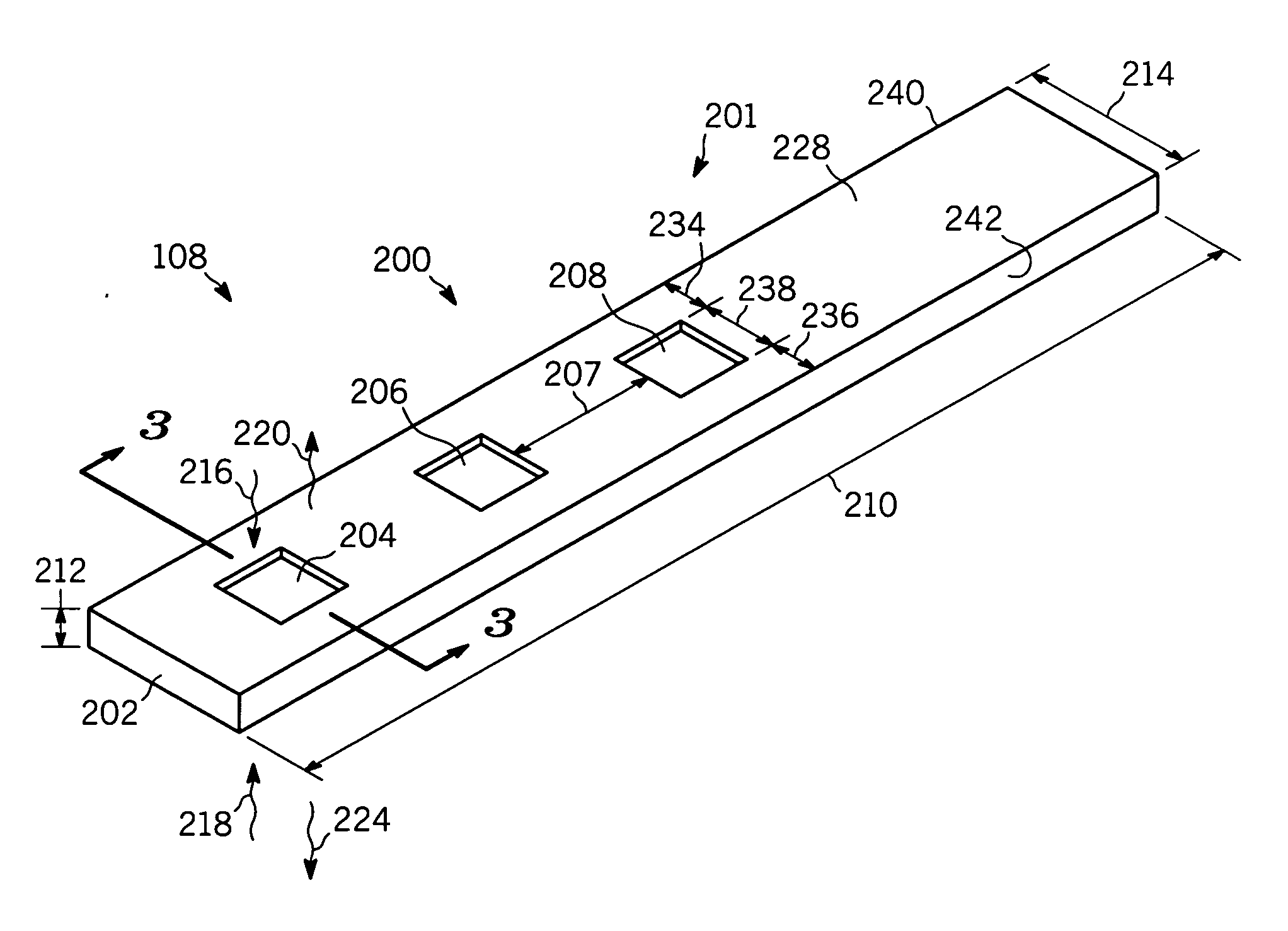
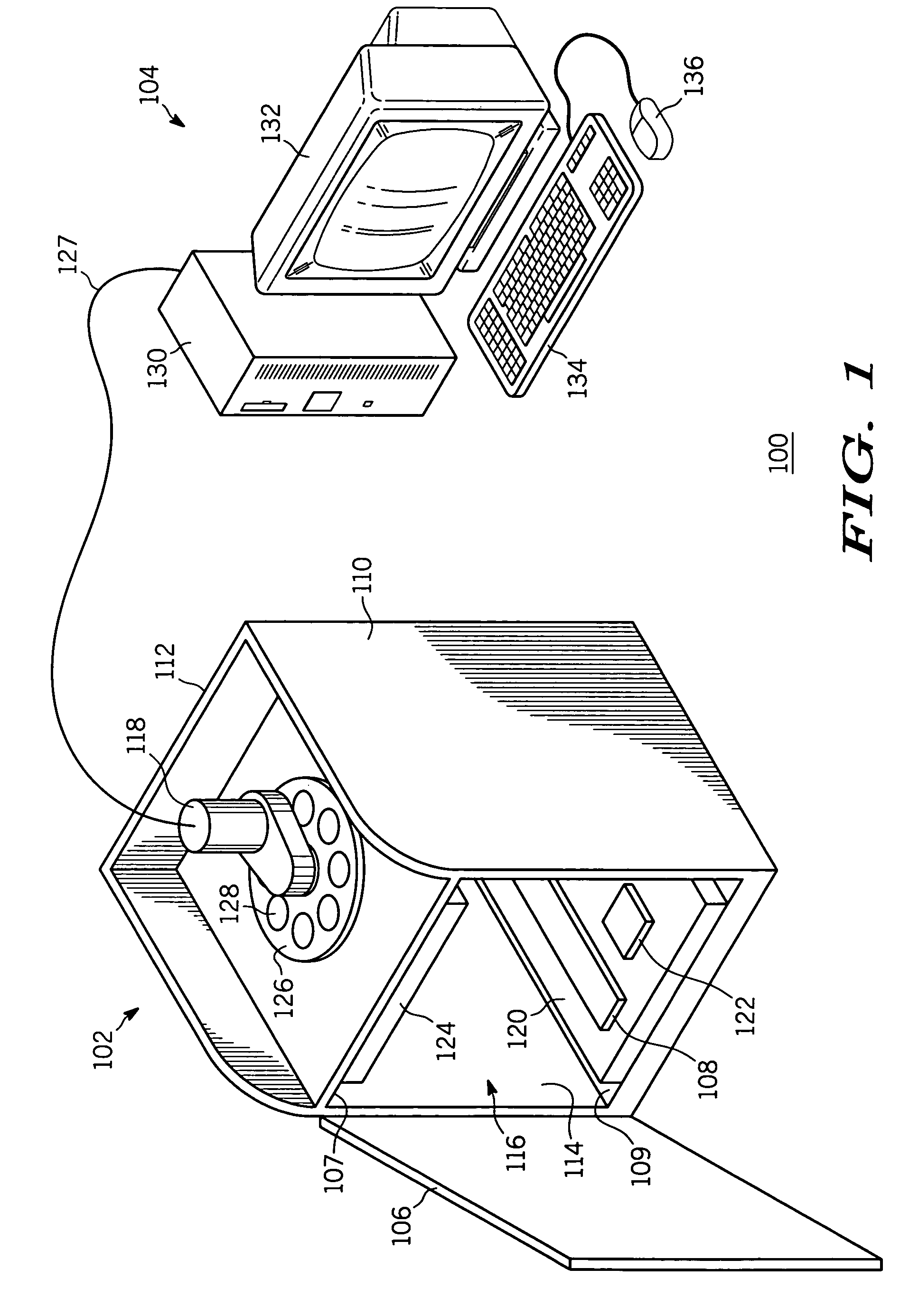
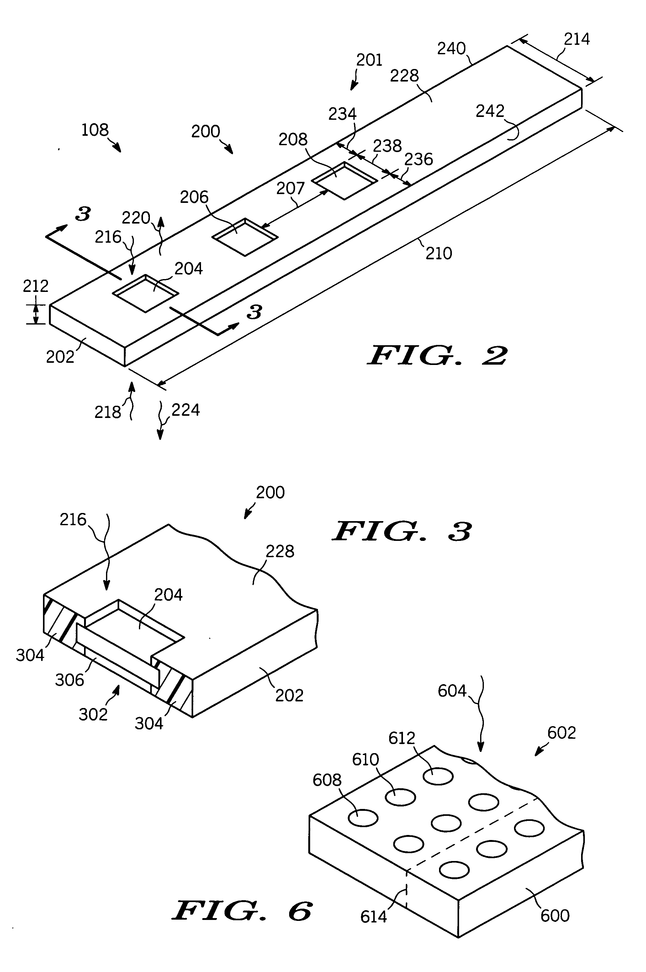
[0079] Example 1 demonstrates that there is system variation over time. In this experiment, luminescent standard 204 and electrophoreses gel 402 are placed into darkroom enclosure 102 and processed as described in FIG. 4 to generate an image and MGL values. (The figure also shows a separate electrophoresis gel 404. The use of this gel is made in next example #2.) After a period of time, electrophoresis gel 402 and luminescent standard 204 are reprocessed as previously described in FIG. 4 and is now shown in FIG. 5 as electrophoresis gel 502.

[0080] For the sake of clarity and simplicity, data from luminescent standard 204 and bands 446 and 526 will be used. The luminescent standard 204 and electrophoresis gel was removed for an X amount of time. The same luminescent standard 204 and same electrophoresis gel (shown as electrophoresis gel 502 on FIG. 5) was put back in the darkroom enclosure 102 and processed a second time.

[0081] The MGL values of luminescent standard 204 and corresp...

example 2

[0084] Example 2 demonstrates the normalization of two different electrophoresis gels 502 and 404. In this example, electrophoresis gel 404 has been processed in the same manner as electrophoresis gel 402 in FIG. 4. MGL values for luminescent standard 204 and bands 446 and 448 have been taken and stored in the memory of computer 130. The data from the luminescent standard 204 in FIG. 4 is identified as (FRS#1). In another experiment accomplished at a later time, electrophoresis gel 502 is generated. Electrophoresis gel 502 and luminescent standard 204 are placed into darkroom enclosure 102 imaged and processed so as to generate data.

[0085] For the sake of simplicity and clarity, the data from luminescent standard 204 taken with electrophoresis gel 502 in FIG. 5 will be identified as (FRS#2) and data from bands 526 and 528 will be used.

[0086] The MGL values recorded as described above are compared as shown in Table 2.

TABLE 2FRSBandBandFRSBandBand(204)(446)(448)(204)(526)(528)MGL2...


PUM


Abstract

A luminescent calibration device (108) is provided with the luminescent calibration device (108) having a housing (202) with a surface (228). The housing (202) has a length (210), a width (214), and a thickness (212). The housing (202) having a luminescent standard (204) disposed on the housing (202). A method for calibrating and normalizing luminescent data across a sample and to normalize data from day to day variations is provided.

Description

FIELD OF INVENTION [0001] This invention relates in general to calibration techniques, and more particularly, to calibration techniques using a luminescent calibration device. BACKGROUND [0002] At present, conventional calibration of optical systems and their target samples can not be done with sufficient accuracy. Typically, in a conventional optical system, calibration of the optical system means determining the lowest or smallest amount of luminescent radiation that can be detected. In the prior art, this is achieved by emitting luminescent radiation and changing an aperture size or limiting the amount of luminescent light that is seen by the detector. When the smallest amount of light is detected, the optical system is considered calibrated. However, while this kind of calibration provides useful information as to sensitivity of the optical system, it does not provide calibration solutions to many different kinds of problems that would make the calibration of the optical system ...

Claims


Application Information

Patent Timeline
Patent Type & Authority Applications(United States)
IPC IPC(8): G01J1/58
CPCG01J1/58G01N21/274G01N21/64G01N21/645
Inventor GALLAGHER, SEANMEHTA, SOHAM
Owner UVP ULTRA VIOLET PRODS
Why Eureka
Try Eureka