Electromagnetic motor to create a desired low frequency vibration or to cancel an undesired low frequency vibration

a technology of electromagnetic motors and electromagnetic springs, applied in the direction of dynamo-electric machines, mechanical energy handling, magnetic circuit shapes/forms/construction, etc., can solve the problems of uneven spring load, frequent service, and application of this device in an audio system

Inactive Publication Date: 2006-09-21
EARTHQUAKE SOUND
View PDF10 Cites 77 Cited by
  • Summary
  • Abstract
  • Description
  • Claims
  • Application Information

AI Technical Summary

Problems solved by technology

The use of springs in this design, requires frequent service as the spring constant tends to change with time.
Additionally, as the moving element moves the springs tend to make noise that is audible when the actuator is in use making application of this device unacceptable in an audio system as a low frequency radiator.
Also, if the actuator is mounted vertically with the centering shaft oriented vertically, the weight of the moving element will exercise an uneven load on the springs.
This misalignment will create heat, reduction of performance and possibly destruction of the actuator.
The “flexure” in this design in simple terms is a spring and thus this design has problems that are similar to those described above with respect to patent '336.
r OFF. Once again this design does not address centering during vertical mounting as gravity will offset the center s

Method used


Image

  • Electromagnetic motor to create a desired low frequency vibration or to cancel an undesired low frequency vibration
  • Electromagnetic motor to create a desired low frequency vibration or to cancel an undesired low frequency vibration
  • Electromagnetic motor to create a desired low frequency vibration or to cancel an undesired low frequency vibration

Examples


second embodiment

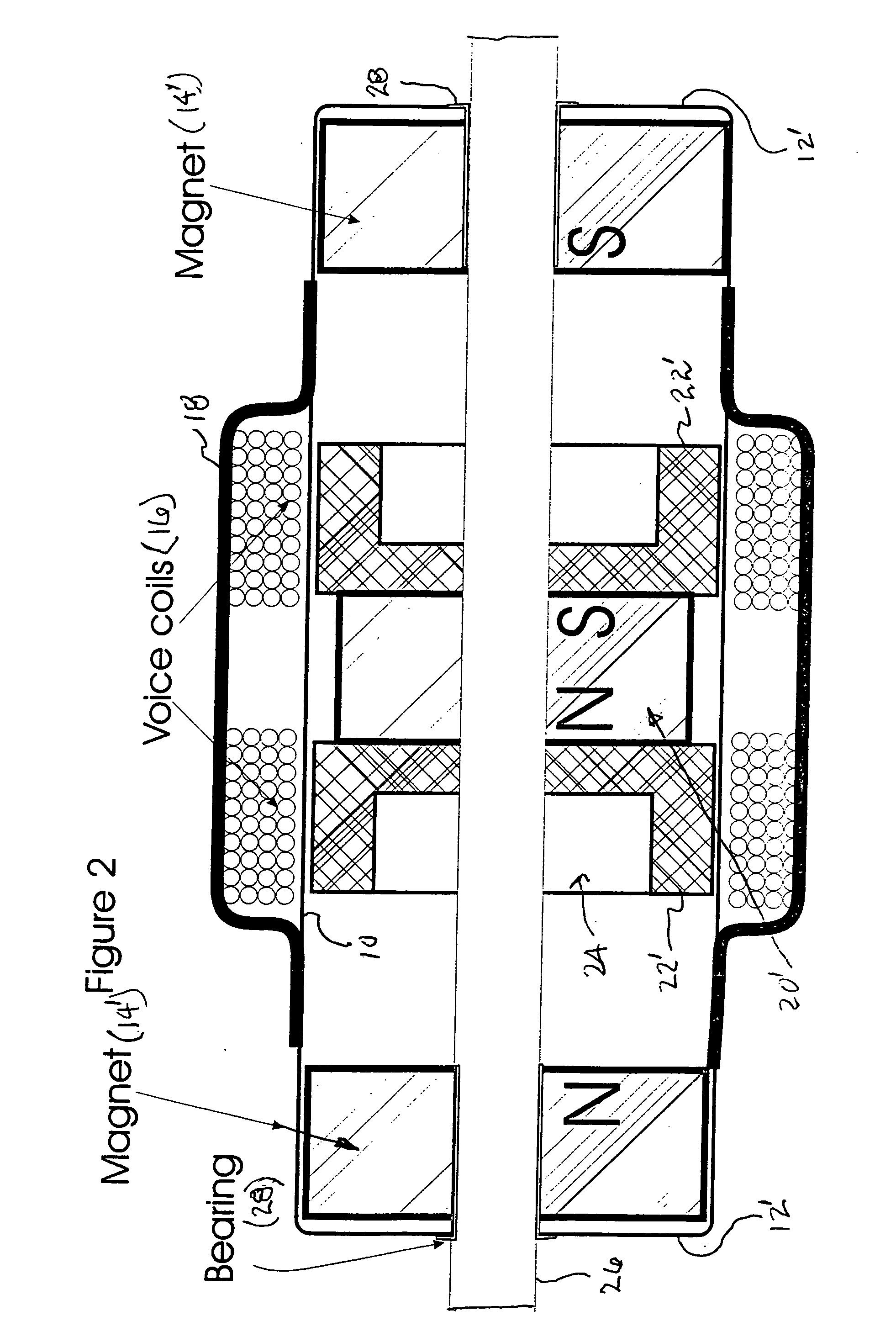
[0037] In FIG. 2 there is shown the present invention. This embodiment is similar to that of FIG. 1 and each of the items that are the same have the same reference number. Here each of the end caps 12′, end magnets 14′, slider magnet 20′ and plates 22′ have a hole through the longitudinal center. Passing through the hole in the center of each of those items is non-ferrous (non-magnetic) rod 26. Additionally there is a bearing in the center hole of end caps 12′ and magnets 14′ with rod 26 passing through bearings 28. The slider (magnet 20′ and plates 22′) is attached to rod 26. With rod 26 being centered and passing through the slider, the slider will always be centered in the diameter of tube10 and thus be prevented from coming into contact with the inner surface of tube 10 when in motion or at rest.

[0038] The overall length of rod 26 depends on the width of slider magnet 20′ and the width of end magnets 12′. The minimum length of rod 26 must be greater than the distance between end...

third embodiment

[0040] Referring next to FIG. 3 there is shown a longitudinal cross-section of the present invention. This embodiment is similar to that of FIG. 2 with the difference being that magnet 20′ and plates 22′ are not affixed to rod 26 and thus able to move on rod 26 when coils 16 are energized; while at the same time the ends of rod 26 are threaded with nuts 32 being tightened to contact each of end caps12′. To reduce wear on non-ferrous rod 26 a bearing 30 can be added around rod 26 and extending into the center holes of magnet 20′ and plates 22′. In this configuration the result is the same regardless whether tube 10 is fastened to a fixed point external tube 10 or rod 26 is fastened to a fixed point external to tube 10 since nuts 32 prevent rod 26 from moving relative to tube 10. Therefore when coils 16 are energized only slider magnet 20′ and plates 22′, magnetically attached thereto, move relative to tube 10.

fourth embodiment

[0041] Next, turning to FIG. 4 there is shown a longitudinal cross-section of the present invention that is similar to the embodiment of FIG. 1 with several additions. Here, as has been done previously, the elements that are the same as those in FIG. 1 have been given the same reference numbers to avoid confusion.

[0042] One of the added features in this embodiment is the external treads 34 on the ends of tube 10 that mate with the internal treads 36 of end caps 12”. The inclusion of threads 34 and 36 permit a fine adjustment of the position of end caps 12″ and thus also end magnets 14 to equalize the magnetic strength exerted by each of end magnets 14 on the slider to accurately center the slider when at rest. Additionally, if the electromagnetic motor of the present invention is mounted vertically on one of end caps 12″ or at an angle with one of end caps 12″ lower than the other, the position of one or both end caps 12″ has / have to be adjusted to also adjust the magnetic forces to...


PUM


Abstract

Electromagnetic motor with a slider that moves linearly with respect to the stator in either direction. Embodiments include slider internal or external the stator. Slider includes one magnetic flux producing element in all embodiments. Internal slider embodiments stator includes a minimum of three magnetic flux producing elements and a maximum of four such elements. External slider embodiments stator includes two magnetic flux producing elements. All embodiments provide positive slider return to center at rest position. In internal slider embodiments the slider is centered within the stator resulting from either: a combination of a repelling force from a single magnetic flux producing element in opposition to gravitational pull on the slider due to its weight; or equal and opposite repelling forces on opposite sides of the stator from a magnetic flux producing element on opposite sides of the stator all three elements in longitudinal alignment with each other.

Description

BACKGROUND OF THE INVENTION [0001] 1. Field of the Invention [0002] The present invention relates to a linear stroke electromagnetic motor having a free moving internal mass that is caused to move selectively by the application of electrical signals to create an electromagnetic force on the free moving internal mass to produce a desired low frequency sound or strong variable vibration or to drive a solenoid like apparatus proportionally to the applied signal. [0003] 2. Description of the Prior Art [0004] The prior art includes various linear stroke electromagnetic motors. An early such device is disclosed in U.S. Pat. No. 4,542,311 (hereinafter '311), issued Sep. 17, 1985 and entitled LONG LINEAR STROKE RECIPROCATING ELECTRIC MACHINE. This device includes a cylindrical air gap defined between outer and inner gaps defining surfaces, at least one of which has a length equal to the length of an electric coil plus the length of the stroke. Additionally it includes a flux focusing ring, ...

Claims


Application Information

Patent Timeline
IPC IPC(8): H02K1/12
CPCH02K33/16
Inventor SAHYOUN, JOSEPH Y.
Owner EARTHQUAKE SOUND
Why Eureka
Try Eureka