
Multiple phase claw pole type motor

Active Publication Date: 2006-09-21
JAPAN SERVO CO LTD +2
View PDF15 Cites 36 Cited by
  • Summary
  • Abstract
  • Description
  • Claims
  • Application Information

AI Technical Summary

Benefits of technology

[0006] An object of the present invention is to provide a multiple phase claw pole type motor with high efficiency having claw poles easily manufacturable.
[0009] According to the present invention, as described above, a multiple phase claw pole type high-efficiency motor having claw poles easily manufacturable can be obtained.

Problems solved by technology

Therefore, the conventional rotating electric motor cannot be obtained as a desirable high-efficiency motor.

Method used


Image

  • Multiple phase claw pole type motor
  • Multiple phase claw pole type motor
  • Multiple phase claw pole type motor

Examples


first embodiment

[0046] Hereafter, a multiple phase claw pole type motor according to the present invention will be described on the basis of FIGS. 1 to 4.

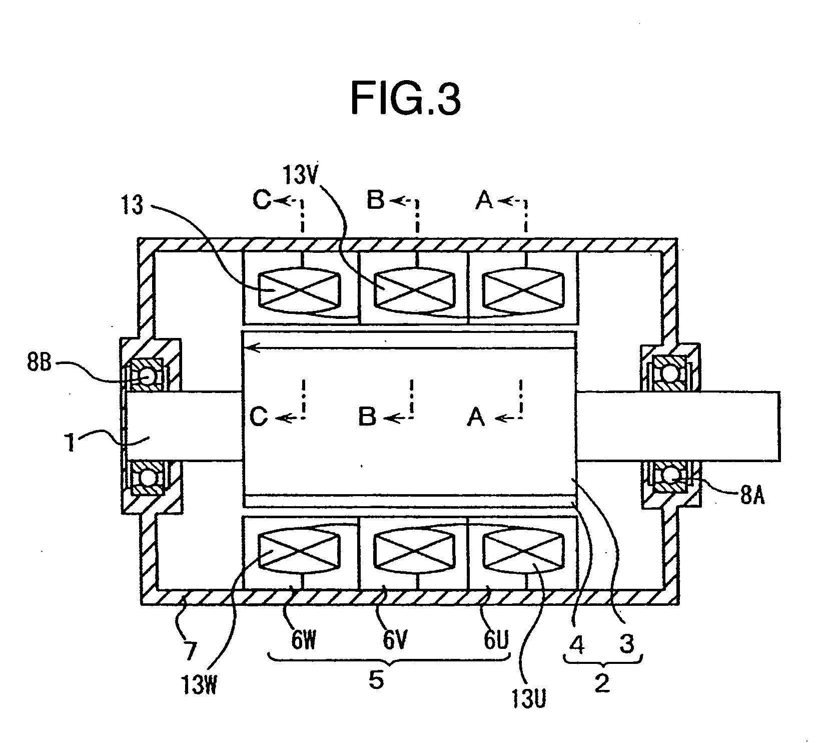
[0047] A three-phase claw pole type motor is constructed by a rotor 2 constructed on a rotating shaft 1, a stator 5 formed concentrically with this rotor 2 in a state of being separated from the same by a small gap formed in a circumferential direction, and a stator frame 7 on which the stator 5 is supported. The rotating shaft 1 is rotatably supported on opposite ends of the stator frame 7 by bearings 8A and 8B.

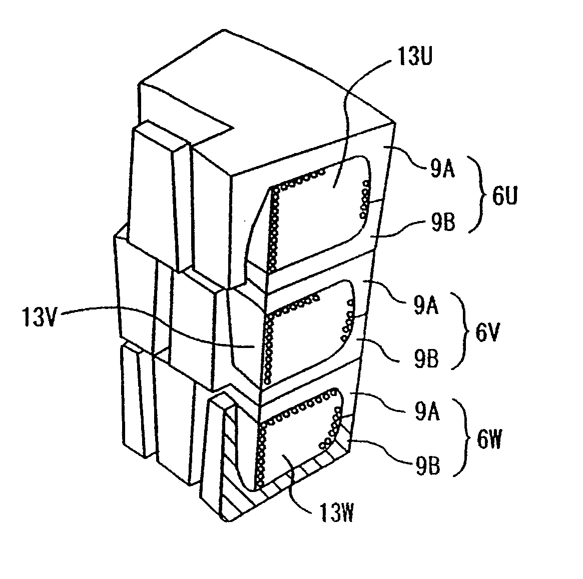
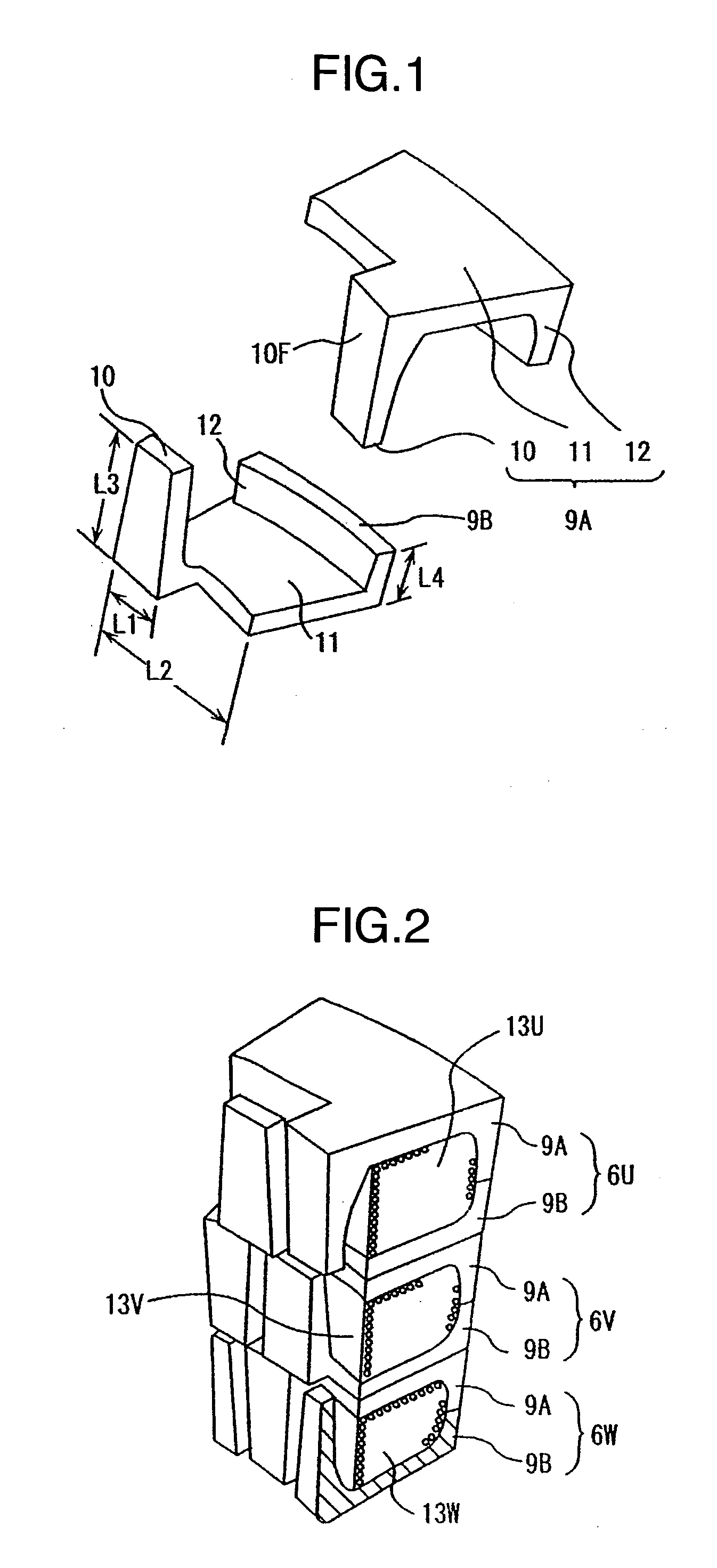
[0048] The rotor 2 is constructed by a rotor iron core 3 formed concentrically with the rotating shaft 1, and a plurality of magnetic poles 4 formed of permanent magnets fixed on the outer periphery of the rotor iron core 3. The stator 5 is constructed by stator iron cores 6U, 6V, and 6W, and annular coils 13 wound on the stator iron cores 6U, 6V, and 6W. The stator iron cores 6U, 6V, and 6W are supported on the stator frame 7, and the ro...

fourth embodiment

[0071] the three-phase claw pole type motor in accordance with the present invention in which the shape of the claw portion 10 is changed to reduce a leakage flux will be described with reference to FIGS. 11 and 12.

[0072] The area of the magnetic pole surface 10F of the claw portion 10 facing the magnetic pole 4 is increased to ensure a high effective value of the linkage flux. The area of the magnetic pole surface 10F is increased by reducing the angle θk in the construction shown in FIG. 1 so that the sides defining the angle θk are parallel to the axial direction. Also, the interpole size SO between the claw portions 10 of each adjacent pair of the first and second claw poles 9A and 9B is increased relative to the gap between the claw portions 10 and the magnetic poles 4, but the interpole size So between portions of the claw portions 10 having a thickness t in the magnetic pole 4 side is reduced.

[0073] If the claw portions 10 are formed in this manner, the flow of the interpole...

fifth embodiment

[0076]FIG. 14 shows the three-phase claw pole type motor in accordance with the present invention.

[0077] In this embodiment, to enable the main flux Φ to flow through the shortest distance, concave portions R1 and R2 formed of polygonal surfaces are respectively formed as an inner corner portion in the connecting portion between the claw pole 9A or 9B and the radial yoke portion 11 and an inner corner portion in the connecting portion between the radial yoke portion 11 and the outer peripheral yoke 12. The concave portions R1 and R2 are formed by connecting a certain number of surfaces at certain angles. They may alternatively be formed of one curved surface or a certain number of curved surfaces.


PUM


Abstract

In a multiple phase claw pole type motor which includes: a plurality of claw poles including a claw portion extending in an axial direction and having a magnetic pole surface facing a rotor in a state of being separated from the rotor by a small gap, a radial yoke portion extending radially outwardly from this claw portion, and an outer peripheral yoke extending from this radial yoke portion in the same direction as the direction of extension of the claw portion; a stator core formed by alternately placing the claw poles in a circumferential direction so that a distal end of each claw portion faces the outer peripheral yoke of an adjacent one of the claw poles; and a stator constructed by sandwiching an annular coil with the adjacent claw poles of this stator core, a multiple phase claw pole type motor characterized in that the claw poles are formed by compacting a magnetic powder and are formed of a magnetic compact having a DC magnetizing property of its flux density becoming 1.7 teslas or more when 10000 A / m of magnetic field is applied.

Description

BACKGROUND OF THE INVENTION [0001] (1) Field of the Invention [0002] The present invention relates to a multiple phase claw pole type motor used in the fields of industry, home electric appliances, motor vehicles, and the like, and, more particularly, to a multiple phase claw pole type motor having an improved stator iron core. [0003] (2) Description of Related Art [0004] Claw pole type iron cores are attracting attention which are provided in ordinary rotating electric motors for the purpose of improving the rate of use of magnetic fluxes by increasing a winding factor of windings, as disclosed in JP-A-2003-333777 for example. [0005] In the conventional rotating electric motor having a claw pole type iron core, claw poles of the iron core are formed by laminating a rolled plate and, therefore, can only be obtained in a simple shape. Therefore, the conventional rotating electric motor cannot be obtained as a desirable high-efficiency motor. BRIEF SUMMARY OF THE INVENTION [0006] An o...

Claims


Application Information

Patent Timeline
IPC IPC(8): H02K1/12
CPCH02K1/02H02K1/145H02K16/04H02K21/145
Inventor ENOMOTO, YUJIITO, MOTOYAMIYATA, KENJIISHIHARA, CHIOMASAKI, RYOSOMOTEGI, YASUAKIISOZAKI, KOUKISATO, TADASHI
Owner JAPAN SERVO CO LTD
Features
  • Generate Ideas
  • Intellectual Property
  • Life Sciences
  • Materials
  • Tech Scout
  • Unparalleled Data Quality
  • Higher Quality Content
  • 60% Fewer Hallucinations
Learn More