
Connector device and checker

a technology of connecting devices and checkers, which is applied in the direction of pipes, couplings, instruments, etc., can solve the problems of inability to dispose checkers, and inability to arrange connectors, etc., and achieve the effect of simple operation

Inactive Publication Date: 2006-09-21
SUMITOMO RIKO CO LTD
View PDF6 Cites 18 Cited by
  • Summary
  • Abstract
  • Description
  • Claims
  • Application Information

AI Technical Summary

Benefits of technology

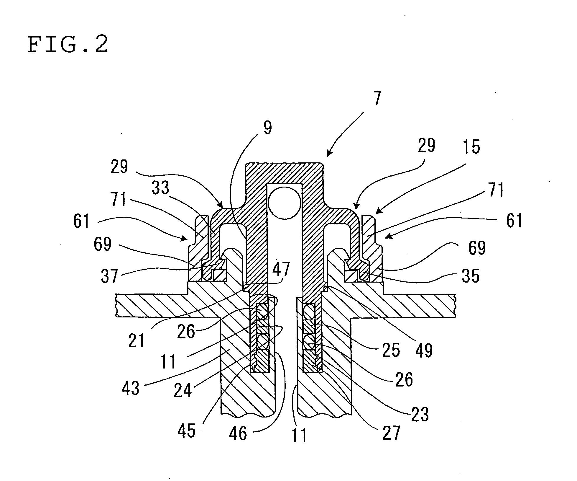
[0010] The protruding stop portion may be provided on an axially inner end portion of the stop arm. And, the verifying recessed portion may be defined in an axially inner end portion (axially inner side) of the verifying portion so as to correspond to the protruding stop portion. Preferably, the verifying portion is configured so as to accommodate the protruding stop portion in the verifying recessed portion while contacting with the outer surface of the stop arm (the phrase “contacting” here includes “a condition just before contacting with the outer surface of the stop arm). In this configuration, since the stop arms are restrained from spreading apart outwardly by the verifying portions, engagement of the engaging pawl with the outwardly directed engaging projection is more strengthened. In addition, it is effective to configure the protruding stop portion or the overhanging stop portion so as to be caught between the verifying recessed portion and the main body on both sides of the protruding stop portion or the overhanging stop portion, when the engaging pawl correctly engages the outwardly directed engaging projection and the checker is installed or disposed. In such construction, since the protruding stop portion is restrained from deformation, specifically when the engaging pawl is provided close to the protruding stop portion, stable engagement between the engaging pawl and the outwardly directed engaging portion can be enhanced. And, it is advantageous to configure the main body so as to enter axially inside the engaging pawl to support the engaging pawl directly or by way of other part of the stop arm.
[0013] As described above, with the connector device of the present invention, the connector can be connected to the connecting hole with simple operation while being stopped from withdrawal, and just in case of incomplete connection, it can be surely detected by means of a checker.

Problems solved by technology

However, when the connecting portion of the connector is not inserted in the connecting hole sufficiently, and the engaging pawl does not pass over the outwardly directed engaging projection, namely, in case of incomplete fit-in relation or incomplete connection, the protruding stop portion is displaced in one axial direction or in a direction away from the connecting hole, and is not located so as to be accommodated in the verifying recessed portion.
So, it is not possible to dispose the checker at the predetermined position.
At less than four angular positions for holding the checker, it is not possible to arrange the connector so as to sufficiently meet a piping arrangement requirement.
On the other hand, at more that twenty angular positions for holding the checker, the anti-rotation structure becomes too complicate and it is feared that the checker is positioned at an angular position different from the predetermined one.

Method used


Image

  • Connector device and checker
  • Connector device and checker
  • Connector device and checker

Examples


Embodiment Construction

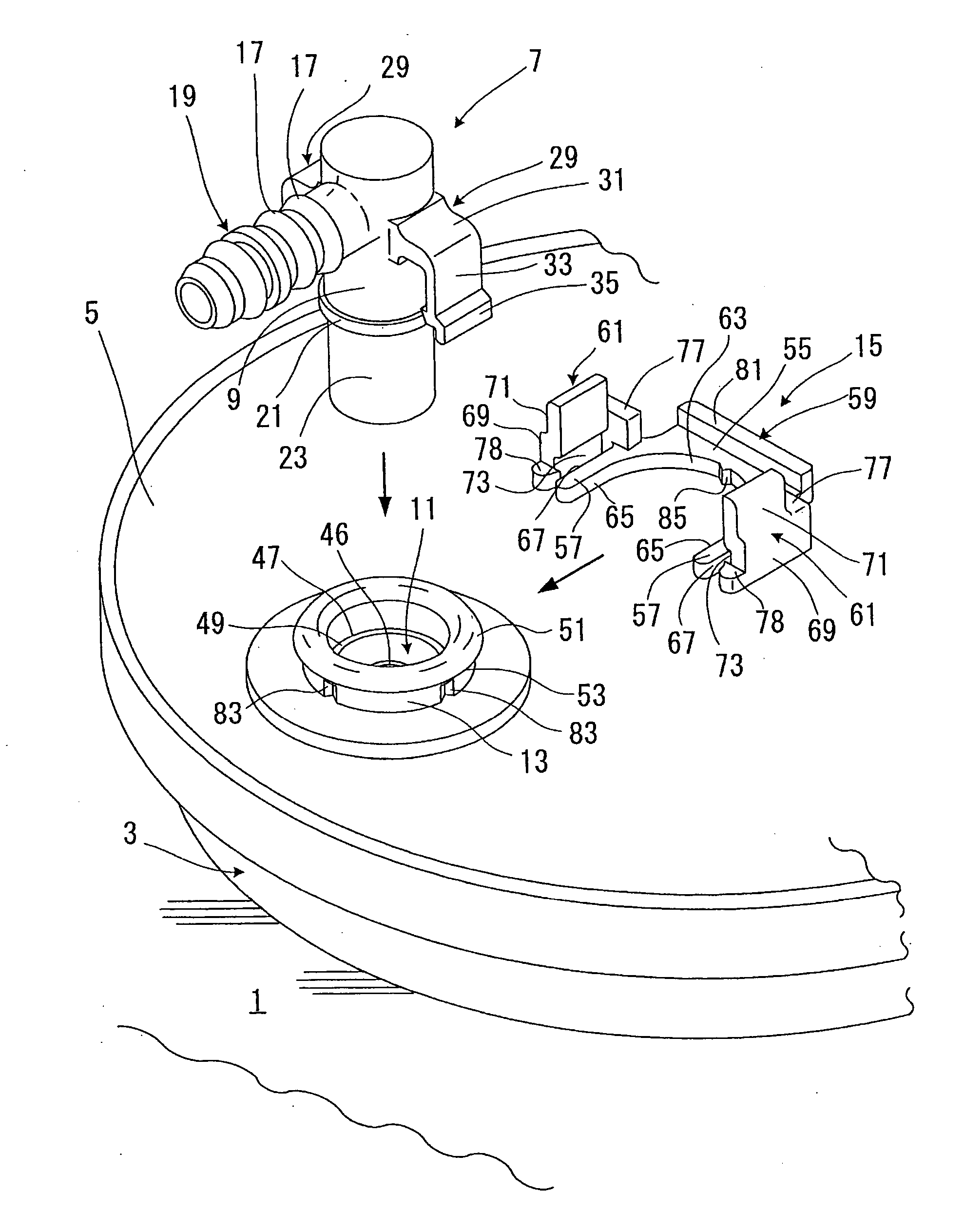
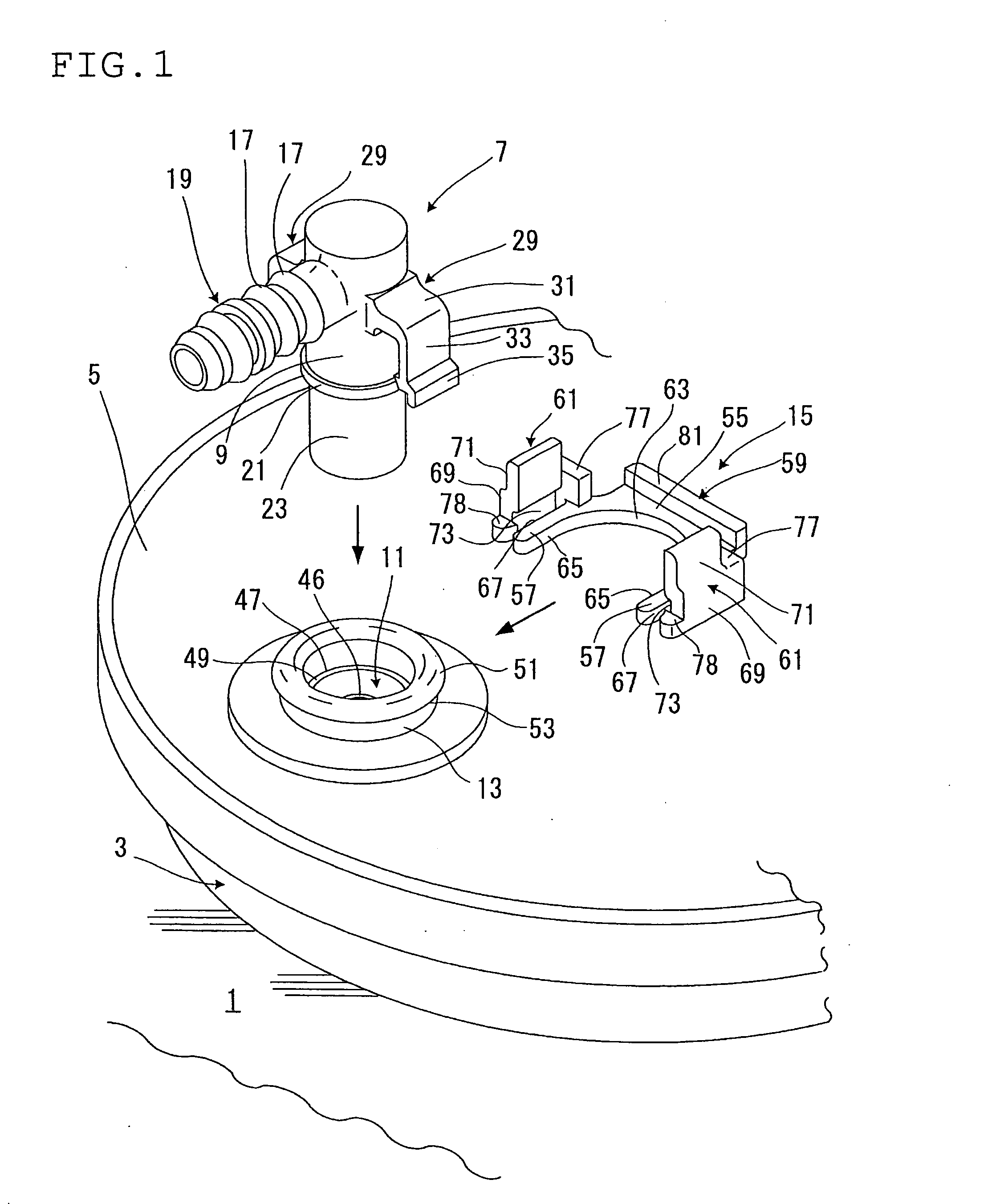
[0023] As well shown in FIG. 1, a fuel tank 1 for a motor vehicle is provided with a fuel pump 3 that has a cap 5, and this cap 5 is formed with a connecting hole 11 in which a tubular connecting portion 9 of a quick connector 7 is inserted. An annular mounting portion 13 is provided on a rim or rim portion of an opening of the connecting hole 11. The quick connector 7 is inserted into the connecting hole 11 via the mounting portion 13, and engages with the mounting portion 13 in locking relation. The quick connector 7 is inserted in the connecting hole 11 in this manner, then a checker (clip) 15 is fitted to an outer circumferential surface of the mounting portion 13 to verify that the quick connector 7 is mounted and connected to the connecting hole 11 or the mounting portion 13 correctly.

[0024] The quick connector 7 in such a connector mounting structure has a tube fit-on portion 19. The tube fit-on portion 19 is formed to be bent out at 90°, namely bent out just laterally on on...


PUM


Abstract

A connecting portion of a quick connector is provided with a pair of stop arms. Each of the stop arms has an arm body that integrally includes an overhanging stop portion and an engaging pawl on a leading end portion thereof. The connecting portion is inserted in a connecting hole formed in a fluid line component until the engaging pawl engages with an outwardly directed engaging projection of a mounting portion that is provided on an opening portion of the connecting hole. A checker has a main body that is provided integrally with verifying portions. Each of the verifying portions is formed with a receiving recessed portion for accommodating the overhanging stop portion therein when the checker is disposed on an outer circumference of the mounting portion.

Description

BACKGROUND OF THE INVENTION [0001] 1. Field of the Invention [0002] The present invention relates to a connector construction that is adapted for connection of a fluid piping of a motor vehicle or the like, for example, a connector device for connecting a tube to a fuel pump of the motor vehicle, and a checker that is used for the connector device. [0003] 2. Description of the Related Art [0004] A gasoline fuel piping of a motor vehicle is constructed by connecting a tube with a fuel pump that is provided on a gasoline fuel tank. The tube is connected with the fuel pump in such manner or mode that a connecting hole is formed in a cap of the fuel pump, a tube is fitted on and connected to a quick connector, and the quick connector with the tube thereon is inserted in and connected to the connecting hole. The quick connector to be used for connecting the tube and the fuel pump integrally has a cylindrical connecting portion and the tube fit-on portion that is formed bent on one end or...

Claims


Application Information

Patent Timeline
IPC IPC(8): G01R31/04
CPCF02M37/0017F16L37/0848F16L2201/10F16L41/08F16L37/0985F16L37/008
Inventor ISHIDA, YOSHIMITSUTAKAYANAGI, AKIRA
Owner SUMITOMO RIKO CO LTD
Learn More