
Patsnap Eureka
For R&D, Patsnap Eureka makes reading and utilizing patents & technical documents easy.
Patsnap Eureka AIR
Designed for self-driven R&D workflows. Generate viable solutions, solve complex R&D challenges, empower your innovation with AI.

Patsnap Eureka Materials
Designed for material experts only. Revolutionize your material R&D, from search, analyze, to developing new materials.

TechResearch
Generate reliable direction feasibility study reports for your R&D in just a few steps.

TechSeek
Discover and master advanced knowledge NOW. Basics, ideas, possibilities, all at once.

TechMind
As an expert in R&D Theories, TechMind can generates customized viable solutions instantly.

TechRisk
Analyze your overall solution with one click, know your potential R&D risks in advance.

TechMonitor
Get weekly tech updates, stay abreast of the latest tech innovations and key insights.
Plasma display panel (PDP)
a technology of display panel and plasma, which is applied in the direction of gas discharge connection/feeding, electric discharge tubes, instruments, etc., can solve the problem of increasing the operating power consumption, and achieve the effect of easy extension
- Summary
- Abstract
- Description
- Claims
- Application Information
AI Technical Summary
Benefits of technology
Problems solved by technology
Method used
Image

Examples
Embodiment Construction
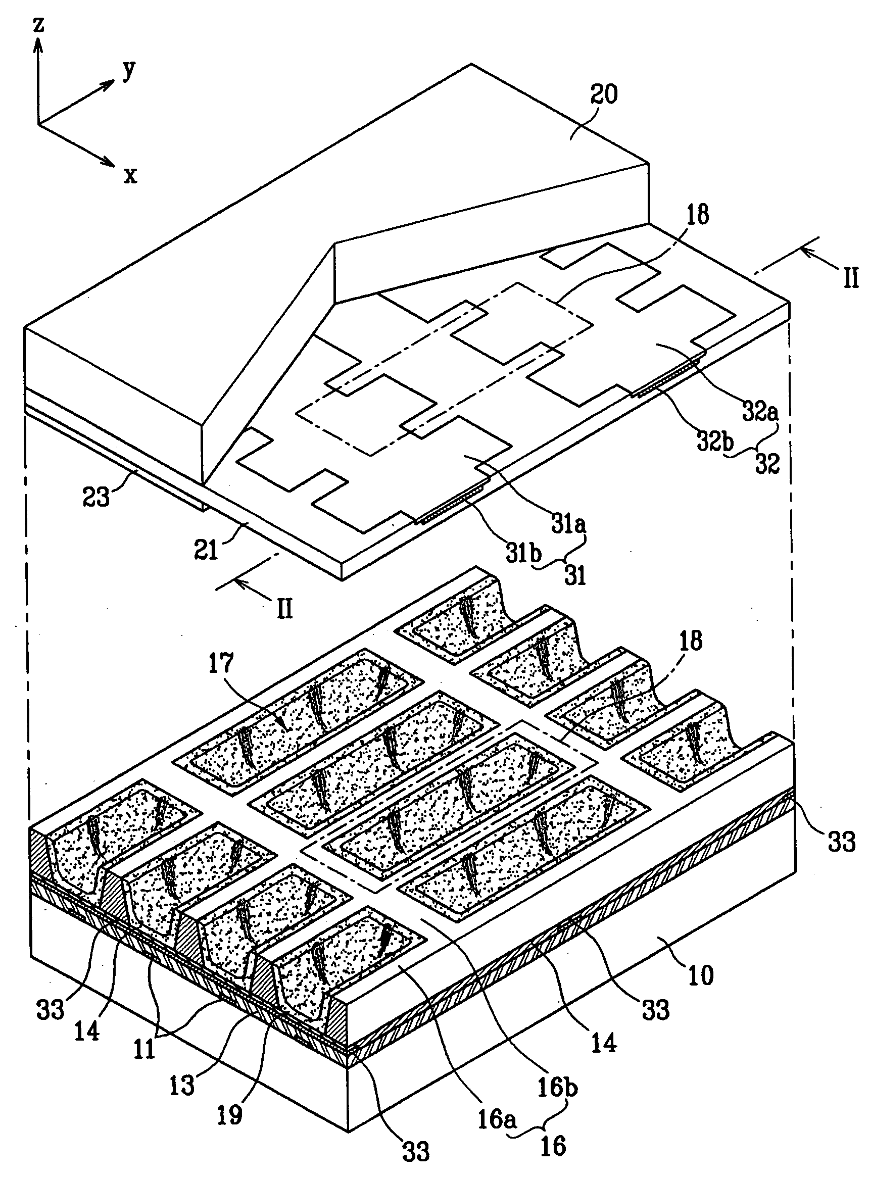
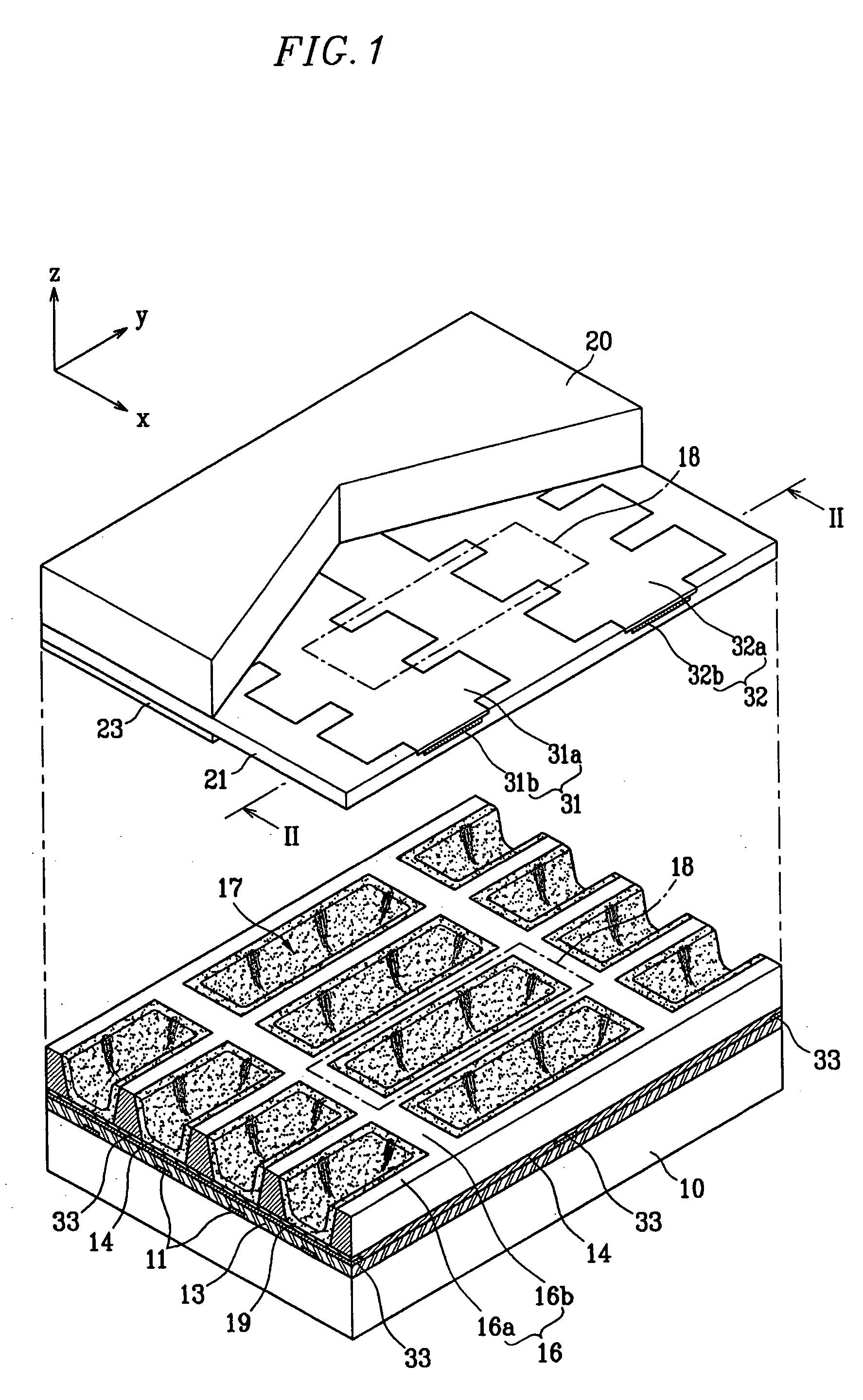
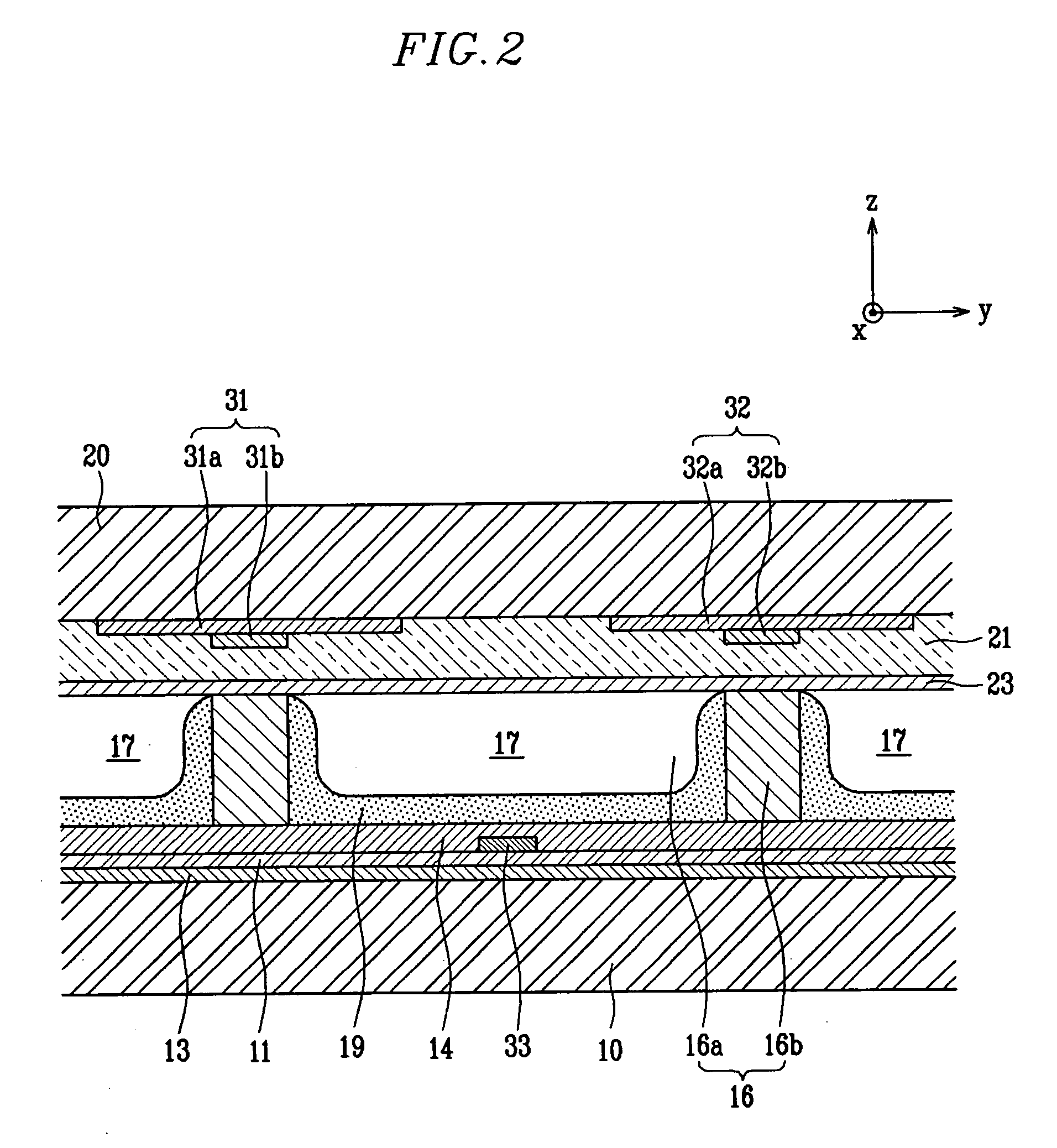
[0029]FIG. 1 is a partial exploded perspective view of a Plasma Display Panel (PDP) according to a first exemplary embodiment of the present invention, and FIG. 2 is a cross-sectional view of an assembled PDP, taken along the line II-II of FIG. 1.
[0030] The PDP includes a first substrate 10 (hereinafter referred to as a ‘rear substrate’) and a second substrate 20 (hereinafter referred to as a ‘front substrate’) facing each other and having a space therebetween, and a barrier rib 16 formed between the rear substrate 10 and the front substrate 20.
[0031] The barrier rib 16 forms discharge cells 18 by partitioning a plurality of discharge spaces 17 between the rear substrate 10 and the front substrate 20.
[0032] The discharge space 17 has a phosphor layer 19 which absorbs vacuum ultraviolet (VUV) rays and radiates visible light, and is filled with a discharge gas, for example, neon (Ne), xenon (Xe), or a mixture thereof, to generate vacuum ultraviolet (VUV) rays by a plasma discharge....
PUM
 Abstract
Description
Claims
Application Information
 - R&D Engineer
- R&D Manager
- IP Professional
- Industry Leading Data Capabilities
- Powerful AI technology
- Patent DNA Extraction
Browse by: Latest US Patents, China's latest patents, Technical Efficacy Thesaurus, Application Domain, Technology Topic, Popular Technical Reports.
© 2024 PatSnap. All rights reserved.Legal|Privacy policy|Modern Slavery Act Transparency Statement|Sitemap|About US| Contact US: help@patsnap.com