Liquid crystal display device and operating method thereof

a liquid crystal display and operating method technology, applied in the direction of electric digital data processing, instruments, computing, etc., can solve the problems of increasing power consumption compared to the line, affecting so as to achieve the effect of improving the quality of the displayed imag

Inactive Publication Date: 2006-09-21
LG DISPLAY CO LTD
View PDF2 Cites 56 Cited by
  • Summary
  • Abstract
  • Description
  • Claims
  • Application Information

AI Technical Summary

Benefits of technology

[0025] An object of the present invention is to provide a liquid crystal display device that improves the quality of a displayed image.

Problems solved by technology

As a result, the fabrication of a large area liquid crystal display panel is difficult.
When an electric field is continuously supplied to the liquid crystal material, the liquid crystal material deteriorates, thereby causing afterimage distortions due to a DC voltage component.
Thus, to set the voltage difference ΔV2 to a value of 5V as in the line inversion method, the image voltage Vdata has to be swung from 0V to 10V, which increases power consumption compared to the line inversion method.
Hence, the common voltage waveforms applied to each pixel are delayed or distorted by the relatively large load.
As can be inferred from FIG. 4, in the in-plane switching mode liquid crystal display device, the resistance of the common electrode provided in each pixel region is high, and the overall resistance of liquid crystal display is high, thus causing a time delay before the applied common voltage VCOM reaches a desired voltage level.
Further, when the common voltage VCOM cannot reach the desired level, the pixels are not charged with a sufficient voltage, thereby deteriorating the quality of the displayed image.

Method used


Image

  • Liquid crystal display device and operating method thereof
  • Liquid crystal display device and operating method thereof
  • Liquid crystal display device and operating method thereof

Examples


Embodiment Construction

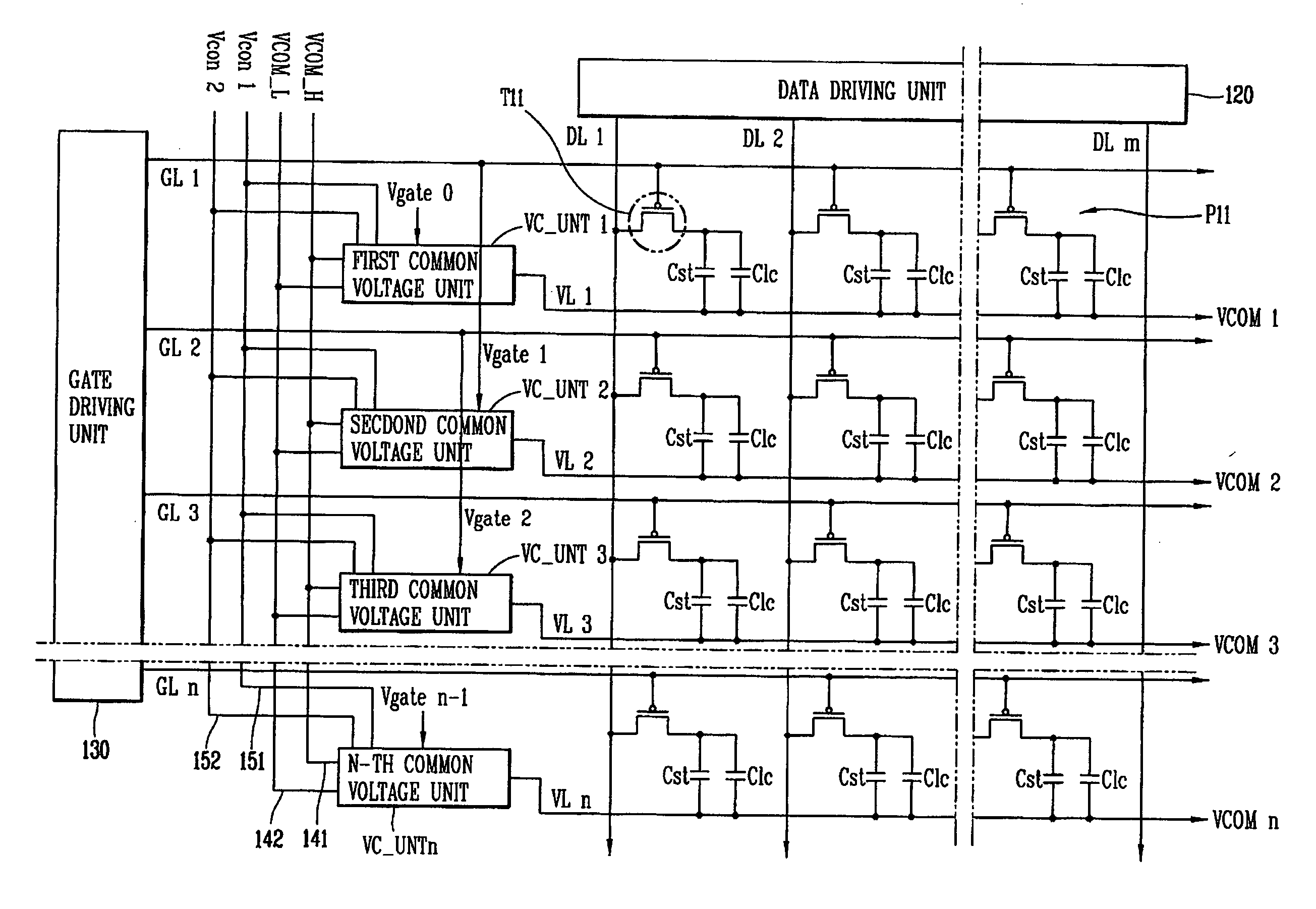
[0044]FIG. 5 is a schematic view of an exemplary driving circuit for a liquid crystal display device in accordance with a first embodiment of the present invention. Referring to FIG. 5, the liquid crystal display device includes a plurality of data lines DL1 to DLm and a plurality of gate lines GL1 to GLn arranged in a matrix on a substrate (not shown) and crossing each other. Crossings of the data lines DL1 to DLm and the gate lines GL1 to GLn define a plurality of pixels P11. A data driving unit 120 is provided for supplying an image voltage to each of the pixels P11 via the data lines DL1 to DLm. A gate driving unit 130 is provided for supplying a scan signal to one or more of the gate lines GL1 to GLn. A plurality of common voltage lines VL1 to VLn is formed on the substrate in a transverse direction to correspond to the gate lines GL1 to GLn. The common voltage lines VL1 to VLn are electrically connected to the pixels P11.

[0045] A thin film transistor (TFT) T11 is provided at ...


PUM


Abstract

A liquid crystal display device includes one or more data line on a substrate; first and second gate lines crossing the one or more data line to form first and second pixels, the one or more data line providing an image signal to a first electrode of each of the first and second pixels, and the first and second gate lines providing first and second scan signals to the first and second pixels, respectively; a first common voltage unit corresponding to the first gate line, the first common voltage unit for selectively applying a first common voltage to a second electrode of the first pixel via a first common voltage line in accordance with one of the first and second scan signals; and a second common voltage unit corresponding to the second gate line, the second common voltage unit for selectively applying a second common voltage to a second electrode of the second pixel via a second common voltage line in accordance with another one of the first and second scan signals.

Description

[0001] This application claims the benefit of Korean Patent Application No. P2004-102593 filed in Korea on Dec. 7, 2004, which is hereby incorporated by reference in its entirety. BACKGROUND OF THE INVENTION [0002] 1. Field of the Invention [0003] The present invention relates to a liquid crystal display device, and more particularly, to a driving circuit for a liquid crystal display device. [0004] 2. Description of the Related Art [0005] In general, a liquid crystal display (LCD) device is formed by attaching a thin film transistor (TFT) array substrate and a color filter (CF) substrate together to face each other with a specified cell gap therebetween, and filling the cell gap with a liquid crystal material. A plurality of gate lines are arranged at regular intervals along a horizontal direction and a plurality of data lines are arranged at regular intervals along a vertical direction on the TFT array substrate to cross each other. Crossings of the data lines with the gate lines d...

Claims


Application Information

Patent Timeline
Patent Type & Authority Applications(United States)
IPC IPC(8): G09G3/36
CPCG09G3/3655G09G2300/0876G02F1/133
Inventor HWANG, HANWOOKKIM, SANGHO
Owner LG DISPLAY CO LTD
Why Eureka
Try Eureka