Confocal microscope

Inactive Publication Date: 2006-09-21
YOKOGAWA ELECTRIC CORP
View PDF6 Cites 30 Cited by
  • Summary
  • Abstract
  • Description
  • Claims
  • Application Information

AI Technical Summary

Benefits of technology

[0014] An object of the invention is to provide a confocal microscope which enables to programmably vary the number

Problems solved by technology

In principle, the light intensity is not uniform between the center and surrounding portions of the illuminating light.
Furthermore, th

Method used


Image

  • Confocal microscope
  • Confocal microscope
  • Confocal microscope

Examples


Embodiment Construction

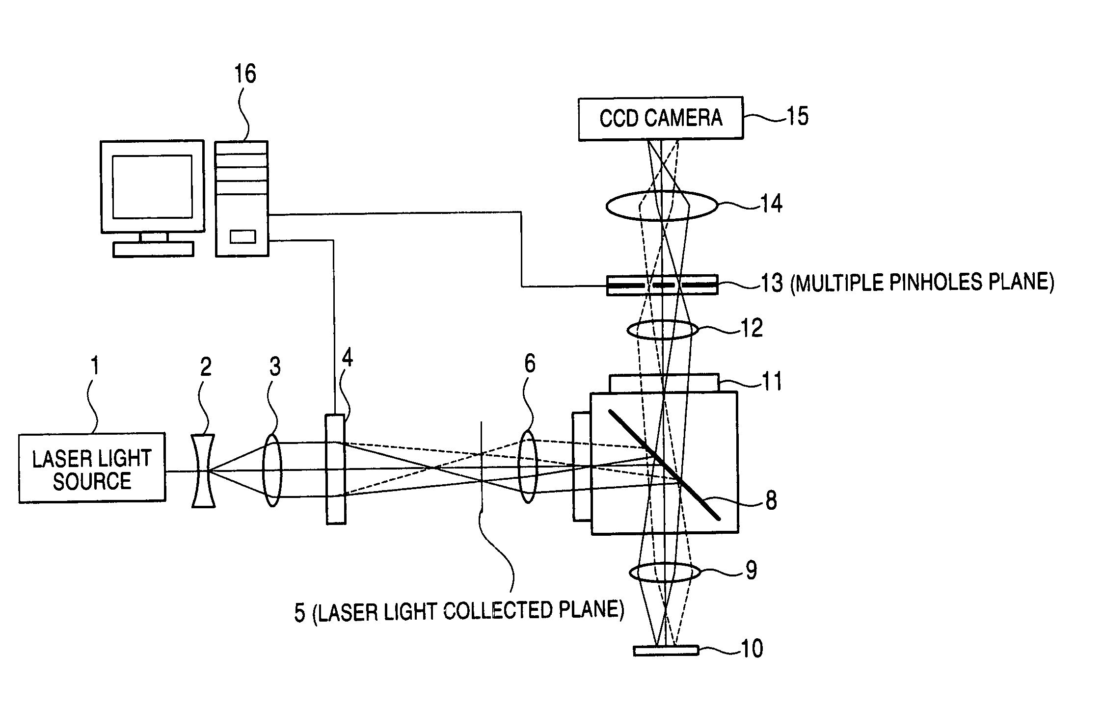
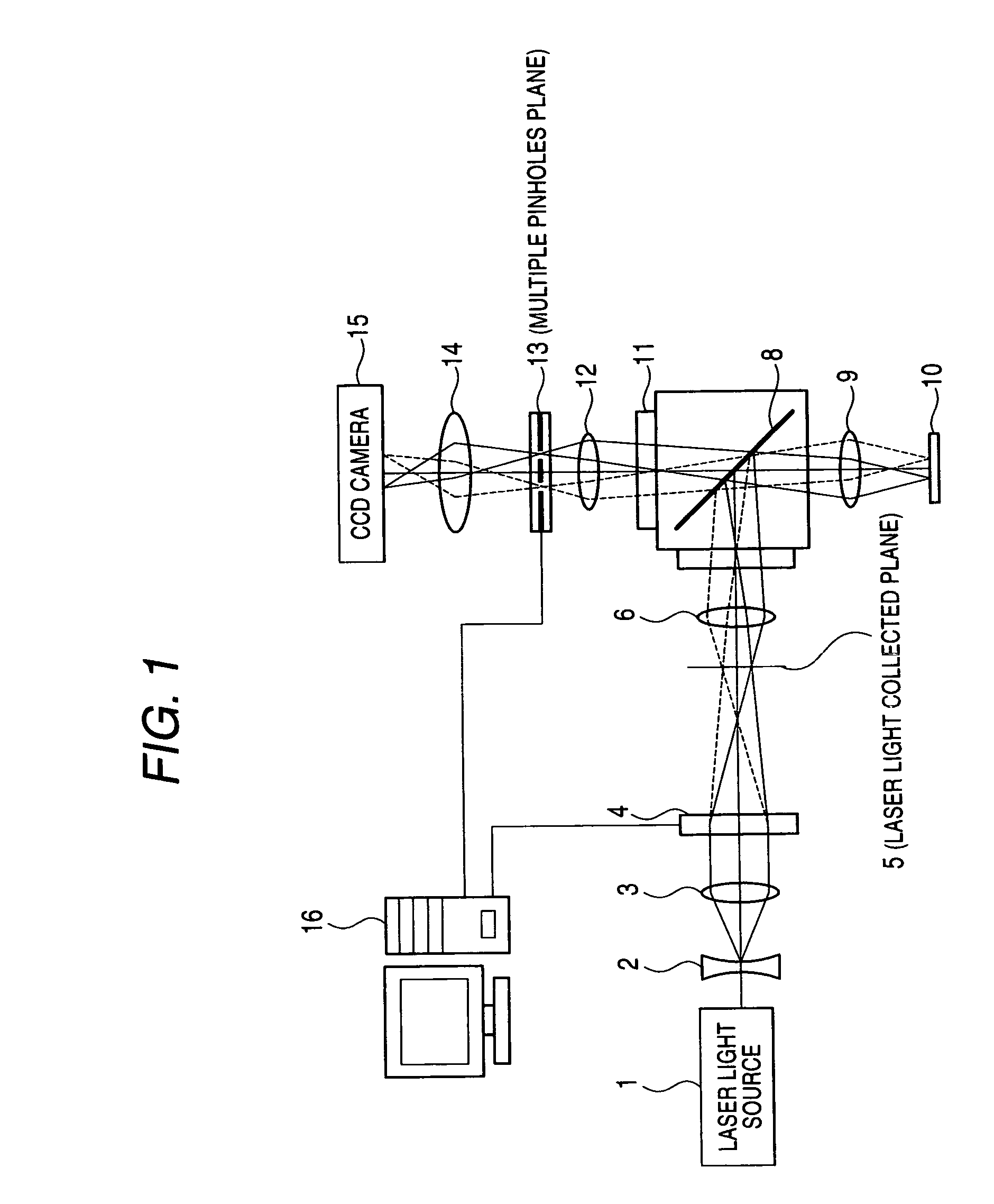
[0025] An embodiment of the present invention is hereinafter described in detail with reference to the drawings. FIG. 1 is a diagram showing an embodiment of a confocal microscope according to the present invention.

[0026] In FIG. 1, a laser light source 1 emits laser light that constitutes exciting light directed at a sample 10. A concave lens 2 and a collimator lens 3 collimate the laser light from the laser light source 1. A phase modulator element 4 phase-modulates the collimated laser light and collects it as a plurality of spotlights onto a plane 5 scanned with multiple laser beams (a laser light collected plane). Thus, a pattern of multiple beam spots is formed. In particular, the phase modulator element 4 comprises a liquid crystal element, for example. Each cell modulates the phase of incident light by voltage control, yielding an efficiency of collection of light comparable to that of a lens. Also, an arbitrary pattern of optical image is collected. In the present embodime...


PUM


Abstract

A confocal microscope uses fluorescent or reflected light obtained by irradiating a plurality of beam spots to a sample so as to observe the sample. The confocal microscope has a phase modulator element which modulates phase of laser light to form the beam spots, a liquid crystal element which forms a plurality of pinholes through which only the fluorescent or the reflected light is transmitted, and a control section which controls the phase modulator element and the liquid crystal element.

Description

CROSS-REFERENCE TO RELATED APPLICATIONS [0001] This application is based upon and claims the benefit of priority from the prior Japanese Patent Applications No. 2005-052320, filed on Feb. 28, 2005, the entire contents of which are incorporated herein by reference. BACKGROUND OF THE INVENTION [0002] 1. Field of the Invention [0003] The present invention relates to a confocal microscope, more particularly to a confocal microscope which enables to programmably vary the number of illumination spots and the pinhole sizes. [0004] 2. Description of the Related Art [0005] A confocal microscope is used to observe a sample by scanning an optical spot focused onto the sample and bringing fluorescent light or reflected light emanating from the sample into a focus to obtain an image. Confocal microscopes are used for observation of physiological reactions in living cells in the biological and biotechnological fields, observation of morphologies, and observation of surfaces of LSIs in the semicon...

Claims


Application Information

Patent Timeline
IPC IPC(8): G02B21/06
CPCG02B21/004G02B21/0044G02B21/0076
Inventor MIKURIYA, KENTAYOSHIDA, TAKASHIKEI, TAKAYUKI
Owner YOKOGAWA ELECTRIC CORP
Why Eureka
Try Eureka