Fiber optic storing and dispensing apparatus

Active Publication Date: 2006-09-21
FIBER OPTIC PROTECTION SYST
View PDF3 Cites 134 Cited by
  • Summary
  • Abstract
  • Description
  • Claims
  • Application Information

AI Technical Summary

Benefits of technology

[0010] The grooves are formed by spaced apart side-by-side flanges, one of which is common to both grooves. An intermediary portion of cable passes from the primary groove in the spool to the secon

Problems solved by technology

The storage of a fiber optic cable in a flimsy plastic bag is undesirable because of the susceptibility to damage of such cable while accommodated in such bag.
Manual uncoiling of the cable frequently causes the cable to become twisted or kinked, whereas manual recoiling of the cable subjects it to the possibility that it will be wound about a radius less than the minimum bending radius, thereby physically damaging the cable and adversely affect its ability to transmit an optical signal without undue attenuation.
In those instanc

Method used


Image

  • Fiber optic storing and dispensing apparatus
  • Fiber optic storing and dispensing apparatus
  • Fiber optic storing and dispensing apparatus

Examples


Embodiment Construction

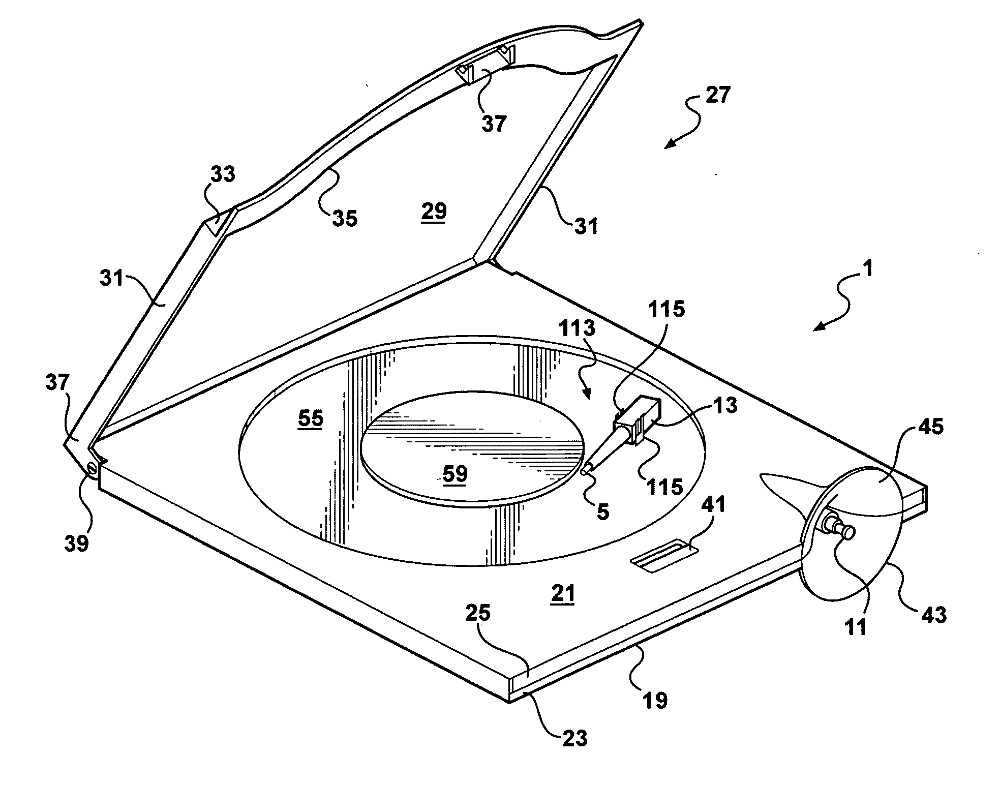
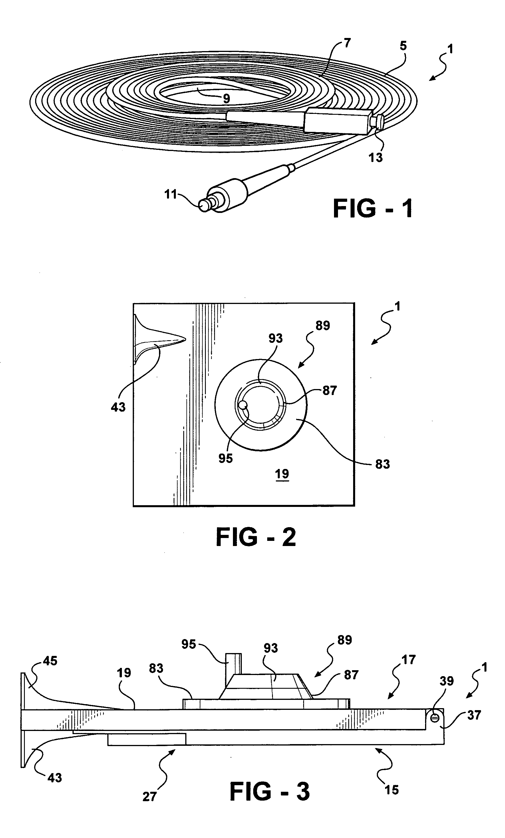
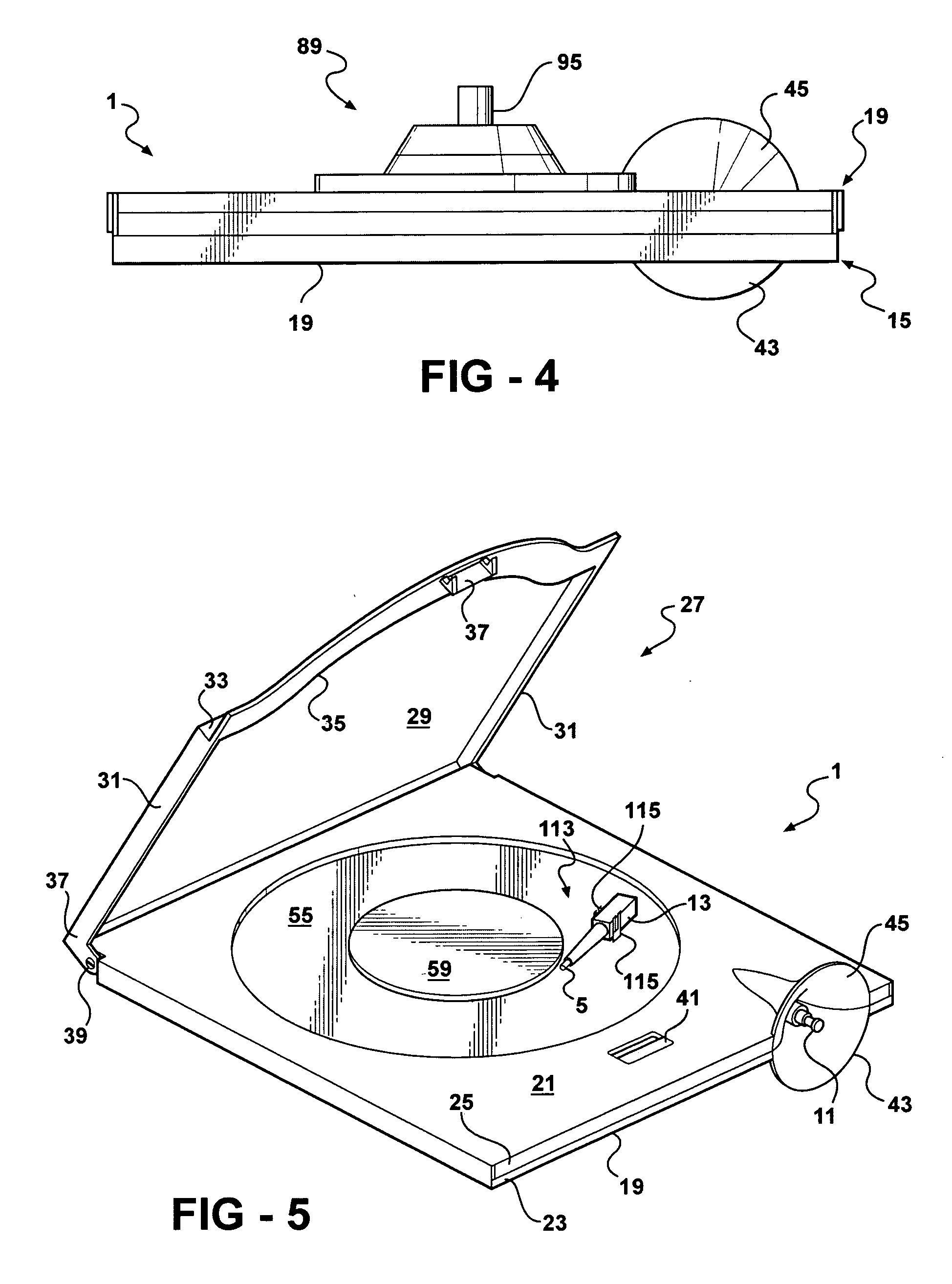
[0024] Apparatus constructed in accordance with the presently preferred embodiment of the invention comprises a casing 1 formed from rigid plastic material, such as polycarbonate or that used in the manufacture of so-called jewel cases for compact discs and the like. The casing is adapted to contain a selected length of coilable material, such as a conventional, cladded fiber optic cable 3. As shown in FIG. 1 the cable 3 is a single, unitary cable having two coil sections 5 and 7 each of which is wound about a radius at least as great as the minimum bending radius of the cable. The section 5 has a length greater than that of the section 7. The longer section 5 sometimes will be referred to herein as the primary section and the shorter section 7 as the secondary section. The cable includes an integral intermediate section 9 which forms a transition between the sections 5 and 7. (The section 9 is lined in FIG. 1 for clarity of illustration, but is identical to the remainder of the cab...


PUM

PropertyMeasurementUnit
Lengthaaaaaaaaaa
Diameteraaaaaaaaaa
Radiusaaaaaaaaaa

Abstract

Storage and dispensing apparatus for use with a unitary length of coilable fiber optic cable having a minimum bending radius, such apparatus having a casing within which is journaled a rotatable spool having two grooves in which relatively long and relatively short lengths of the cable may be coiled. One end of the cable is coupled to a connector that is releasably retained on the spool for rotation therewith. The opposite end of the cable is joined to a connector which is extendible from and retractable into the casing in which the spool is journaled. The casing is formed of rigid plastic material which protects the cable against damage from externally applied forces. No part of the cable within the casing is subject to being bent about a radius less than the minimum bending radius.

Description

[0001] This invention relates to apparatus for storing and dispensing coilable material, such as a fiber optic cable, in and from a protective casing. BACKGROUND OF THE INVENTION [0002] When installing, testing, maintaining, or tuning all ranges of fiber optic networks it is necessary to use various test sets. A test set ordinarily will include one or more fiber optic jumper cables for verifying the integrity of signal flow through various parts of the fiber optic circuit. The length of the fiber optic jumper cable depends on the distance that must be spanned by such cable. [0003] A fiber optic jumper cable used for testing purposes in the field conventionally is accommodated for shipment in a transparent, flimsy, plastic storage bag. Conventionally, a jumper cable is wound about a radius of two inches or more to form a coil which is placed in the plastic bag without any additional protection against damage from externally applied forces, such as that resulting from being stepped on...

Claims


Application Information

Patent Timeline
IPC IPC(8): G02B6/00
CPCG02B6/4453G02B6/4457
Inventor KLINE, JAMES R.KLINE, THOMAS J.SENE, DUSTIN S.
Owner FIBER OPTIC PROTECTION SYST
Why Eureka
Try Eureka