Fixed constant velocity universal joint

Active Publication Date: 2006-09-21
NTN CORP
View PDF12 Cites 6 Cited by
  • Summary
  • Abstract
  • Description
  • Claims
  • Application Information

AI Technical Summary

Benefits of technology

[0008] In the fixed constant velocity universal joint, when torque is transmitted at an operating angle, a ball moves in a cage pocket in the circumferential direction as well as radial direction of the cage. In the fixed constant velocity universal joint using six balls, a thickness of a cage satisfies a radial movement of the balls w

Problems solved by technology

This is due to the fact that an increase in cage thickness makes ball grooves of outer and inner rings shallower, thereby decreasing fatigue life of the joint at high angles and high loads.
However, as the thickness of the cage is increased, the depth of the ball grooves o

Method used


Image

  • Fixed constant velocity universal joint
  • Fixed constant velocity universal joint
  • Fixed constant velocity universal joint

Examples


Example

[0036] First, a BJ type in accordance with an embodiment shown in FIGS. 5 to 7 will be described. As shown in the figures, a fixed constant velocity universal joint includes an outer ring 10, an inner ring 20, balls 30 and a cage 40.

[0037] The outer ring 10 as an outer joint member is in the shape of a cup or bell and includes a shaft part 18 on its closed end side for connection with one of two shafts to be coupled. The outer ring 10 has a spherical inner circumferential surface, that is, inner sphere 12 and eight arcuate ball grooves 14 extending in the axial direction are formed in the inner sphere 12 in the circumferential direction at regular intervals.

[0038] The inner ring 20 as an inner joint member has a serrated or splined hole 28 for connection with the other of the two shafts to be coupled, here, a shaft 5. The inner ring 20 has a spherical outer circumferential surface, that is, outer sphere 22 and eight arcuate ball grooves 24 extending in the axial direction are form...


PUM


Abstract

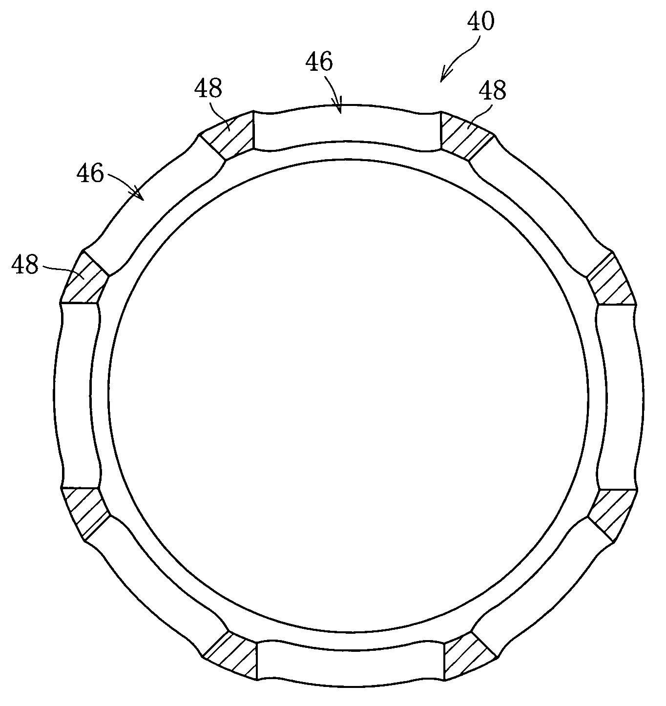
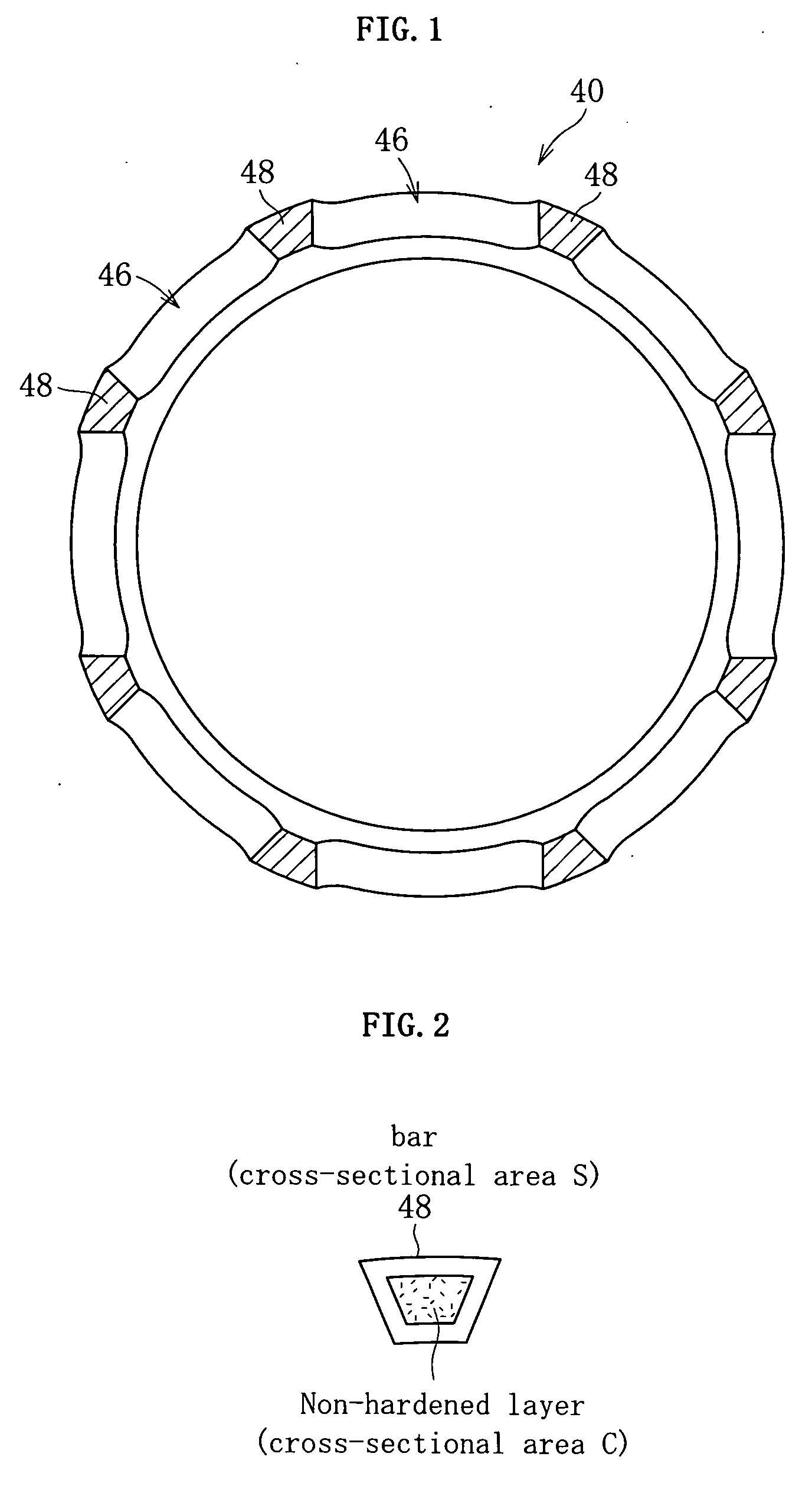
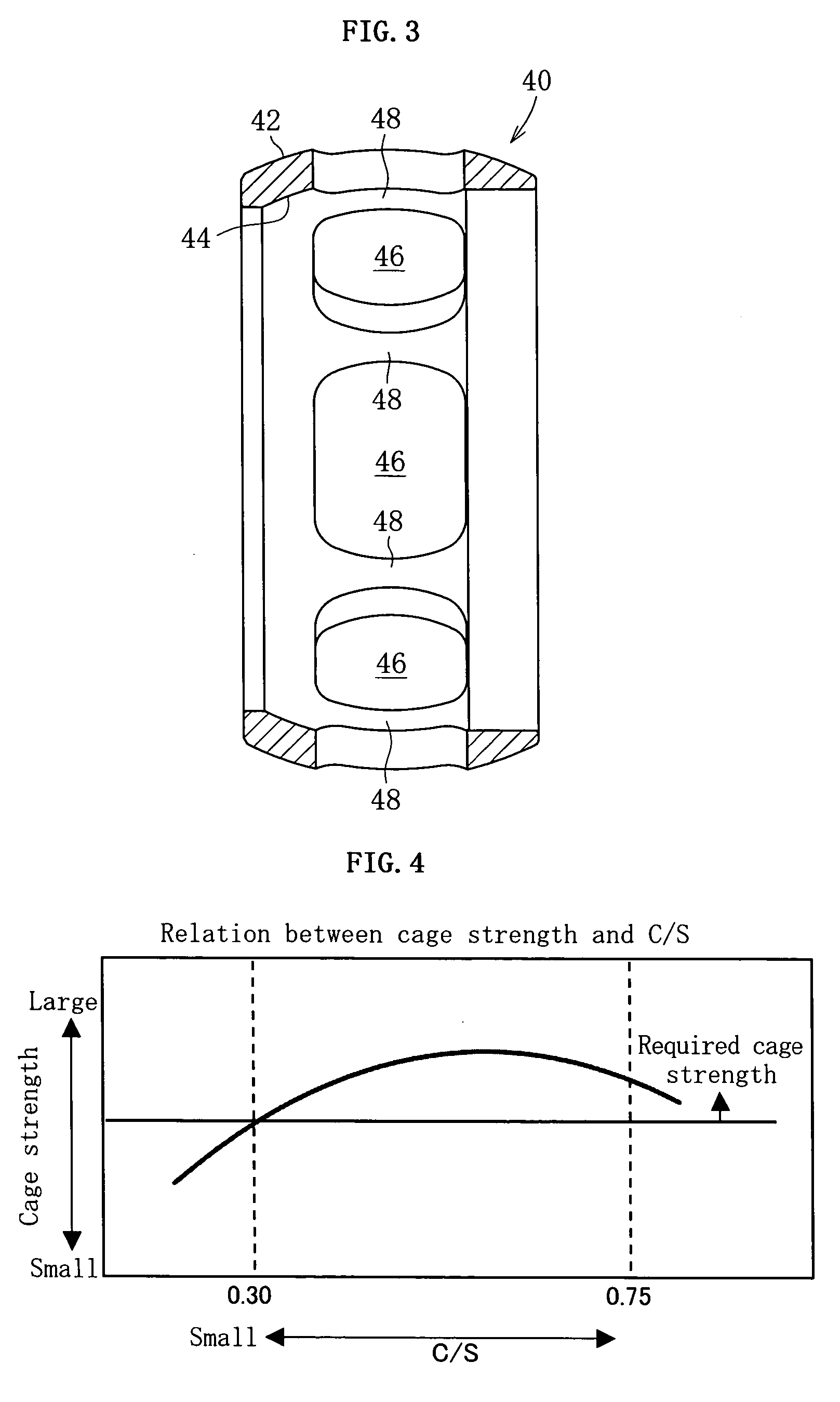
A fixed constant velocity universal joint using eight torque transmitting balls hasa ratio which a non-hardened layer assumes in a bar 48 of a cage 40 is set to be 0.30≦C/S≦0.75, where S represents a cross-sectional area of the bar 48 and C represents an area of the non-hardened layer.

Description

BACKGROUND OF THE INVENTION [0001] 1. Field of the Invention [0002] The present invention relates to a fixed constant velocity universal joint for use in automobiles and various industrial machines and, more particularly, to a fixed constant velocity universal joint using eight balls as torque transmitting elements. [0003] 2. Description of the Background Art [0004] Constant velocity universal joints are classified into fixed joints which cannot slide and sliding or plunging joints which can slide in the axial direction thereof. FIGS. 14 and 15 show a Rzeppa constant velocity universal joint (hereinafter referred to as BJ-type) as a typical fixed constant velocity universal joint. This fixed constant velocity universal joint is comprised of an outer ring 1 as an outer joint member having six axially extending arcuate ball grooves 1b formed in a spherical inner surface 1a thereof, an inner ring 2 as an inner joint member having six axially extending arcuate ball grooves 2b formed in ...

Claims


Application Information

Patent Timeline
IPC IPC(8): F16D3/34F16D3/2237F16D3/2245
CPCF16D3/2237F16D3/2245F16D2003/22303F16D2003/22309F16D2300/10Y10S464/906Y10S464/902
Inventor SUZUKI, TADASHIMURAYAMA, MASARUKOBAYASHI, MASAZUMI
Owner NTN CORP
Why Eureka
Try Eureka