System for automatically inflating temperature regulated blankets and a blanket for coupling to the system

a technology of temperature regulation and blanket, which is applied in the field of automatic inflating temperature regulation blankets and blanket coupling systems, can solve the problems of expensive sensors, requiring an accompanying feedback circuit, and affecting the heating effect of blankets

Inactive Publication Date: 2006-09-21
SMITHS MEDICAL ASD INC
View PDF4 Cites 25 Cited by
  • Summary
  • Abstract
  • Description
  • Claims
  • Application Information

AI Technical Summary

Benefits of technology

[0009] A third embodiment of the instant invention comprises a system that has a patient warming blanket including an inflatable body, an inlet for providing fluid path to the body, and a code positioned on the body for providing an indication of the flow rate of air required to optimally inflate the body. The third embodiment system further includes a convective warmer that has an outlet for mating to the inlet of the blanket, a heater for heating air in a plenum, an air blower for directing the heated air to the outlet, at least one sensor located relative to the outlet for reading the code, and a valve that can regulate the amount of heated air from the air blower to the outlet at a given time, so that when the blanket is coupled to the warmer, a signal representative of the code read by the sensor is used to control the valve for selectively regulating the output of the heated air at an amount that corresponds to the flow rate specified by the code.

Problems solved by technology

However, if the convective warmer were to be used to provide heated air to a pediatric warming blanket, which has a smaller dimension than a regular adult blanket, a special hose has to be fitted to the convective warmer so that a portion of the heated air is either blocked or bypassed from the blanket.
For such a feedback system, an expensive sensor, and an accompanying feedback circuit are required.

Method used


Image

  • System for automatically inflating temperature regulated blankets and a blanket for coupling to the system
  • System for automatically inflating temperature regulated blankets and a blanket for coupling to the system
  • System for automatically inflating temperature regulated blankets and a blanket for coupling to the system

Examples


Embodiment Construction

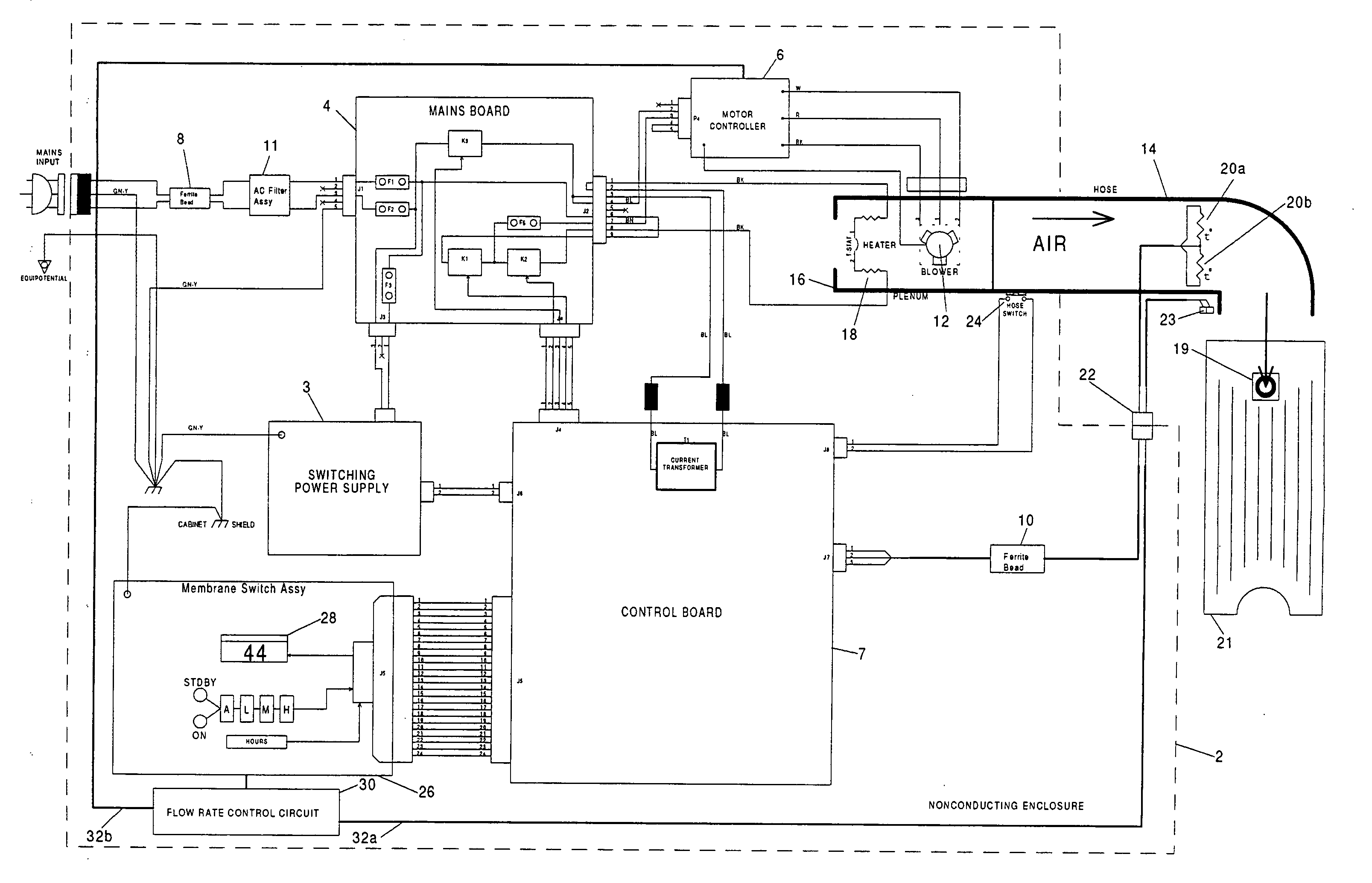
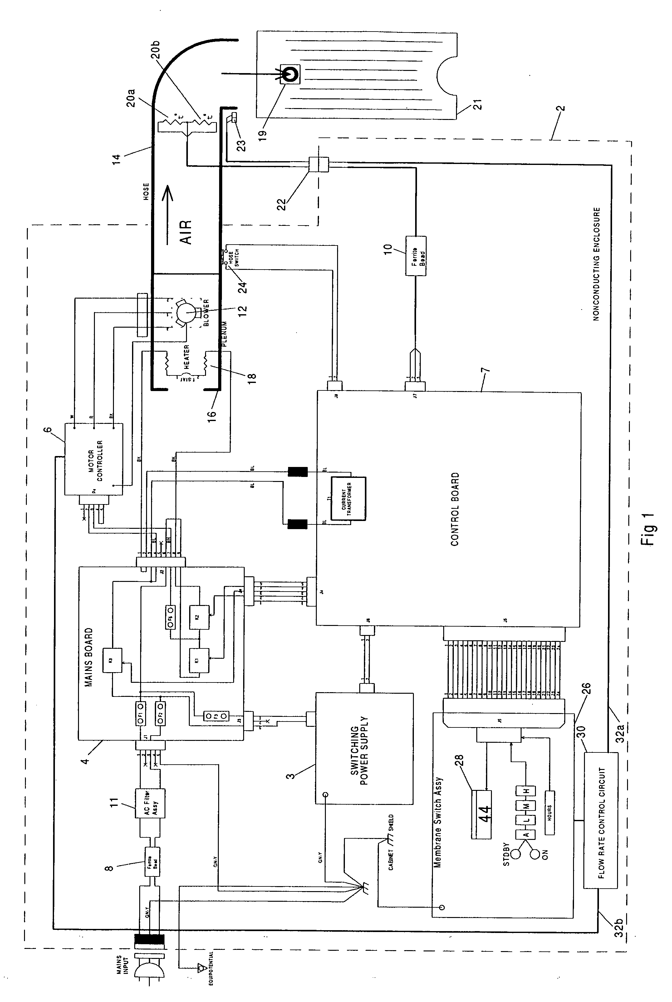
[0018] With reference toFIG. 1, the convection warmer of the instant invention, shown enclosed by the enclosure designated by dotted line 2, includes a switching power supply 3 and a mains board 4. Mains board 4 includes fuses (f) and relays (k) that are used to supply power to both a motor controller 6 and a control board 7. To prevent conductive emission, a ferrite bead 8 is provided at the input of the AC power, and another ferrite bead 10 is provided at the output of the control board. An AC filter assembly 11 filters out transients from the AC power line.

[0019] Motor controller 6, with power provided from mains board 4, controls the operation of an air blower 12 which, for the purpose of this invention, may be considered a fluid mover that moves, directs or blows a fluid such as air to an outlet hose 14. Blower 12 is shown to be located in a plenum 16, which also has resided therein a heater 18 for heating the air being blown by the blower 12 to hose 14, which is connected to ...


PUM


Abstract

A convective warmer to which blankets of different dimensions may be connected is capable of providing air to the various blankets at flow rates that optimally inflate those blankets to achieve the optimal clinical result for the patients covered by those blankets. The blanket connected to the warmer may range from a full size adult warming blanket to a pediatric or neonate warming blanket. There is provided on each blanket a code, marking or marker, to be read by a sensor(s) provided at the outlet of the warmer, that identifies the type of blanket when the blanket is coupled to the warmer. Consequently, heated air may be automatically output by the warmer to the blanket at the appropriate flow rate of that blanket to optimally inflate the blanket without any need for intervention by a user. In addition to being used to control the flow rate of the heated air, the code from the blanket may also be used to control the temperature of the heated air to be input to the blanket.

Description

FIELD OF THE INVENTION [0001] The present invention relates to warming blankets and to a system adapted to optimally inflate each of a plurality of warming blankets irrespective of the different dimensions of those blankets. The present invention more particularly relates to a system that automatically and optimally inflates a warming blanket when the blanket is coupled to the system. BACKGROUND OF THE INVENTION [0002] To hypothermically warm a patient, a convective warmer to which a warming blanket is connected is used. There are various convective warming blanket types that exist in the market today. The various blankets have different dimensions. Prior to the instant invention, a convective warmer, such as the current Level 1 Equator™ warmer, operates at only one speed, so that the same amount of air is output from the warmer irrespective of the size of the blanket connected to the warmer. [0003] Insofar as the different blankets have different sizes, as for example from a full a...

Claims


Application Information

Patent Timeline
Patent Type & Authority Applications(United States)
IPC IPC(8): A61F7/00
CPCA47G9/0215A61F7/0085A61F7/0097A61F7/02A61F2007/006G06K7/10871G06K7/14G06K19/06009
Inventor FREY, WILLIAM E.PIERRE, JOSEPH
Owner SMITHS MEDICAL ASD INC
Why Eureka
Try Eureka