Method for designing formation tester for well

a well-designed and well-designed technology, applied in the direction of seismology for waterlogging, instruments, borehole/well accessories, etc., can solve the problems of large hydrocarbon production, incomplete test, insufficient data for good analysis

Inactive Publication Date: 2006-09-21
HALLIBURTON ENERGY SERVICES INC
View PDF4 Cites 9 Cited by
  • Summary
  • Abstract
  • Description
  • Claims
  • Application Information

AI Technical Summary

Benefits of technology

[0010] In another embodiment, the test chamber may be an open chamber test. The simulation of the present invention may be used to determine perfor

Problems solved by technology

The conventional open flow drillstem tests often result in production of large quantities of hydrocarbons when facilities have not yet been installed for handling such quantities.
However, if the closed-chamber system is no

Method used


Image

  • Method for designing formation tester for well
  • Method for designing formation tester for well
  • Method for designing formation tester for well

Examples


Embodiment Construction

[0014] In the description of the embodiments, various elements may be described as being above or below, or up-hole or down-hole from, other elements. Such references are made with reference to the normal positioning of elements in a vertical borehole. However, the embodiments may also be used in deviated or horizontal boreholes, in which case above or up-hole means closer to the surface location of a well and below or down-hole means closer to the end of the well opposite the surface location, even though the two elements may be at the same vertical elevation.

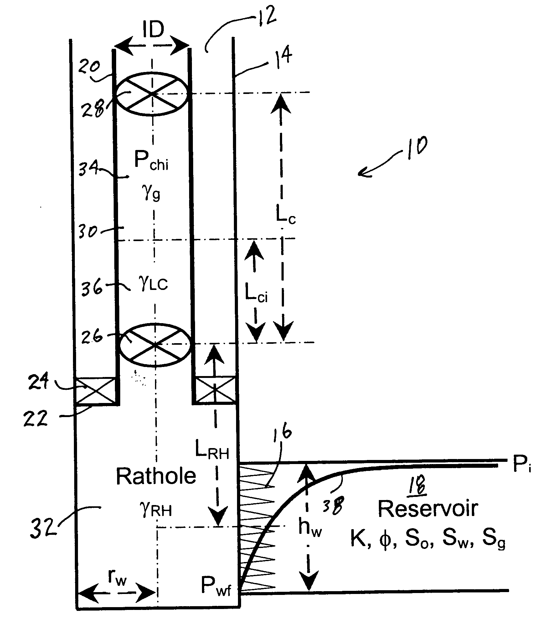
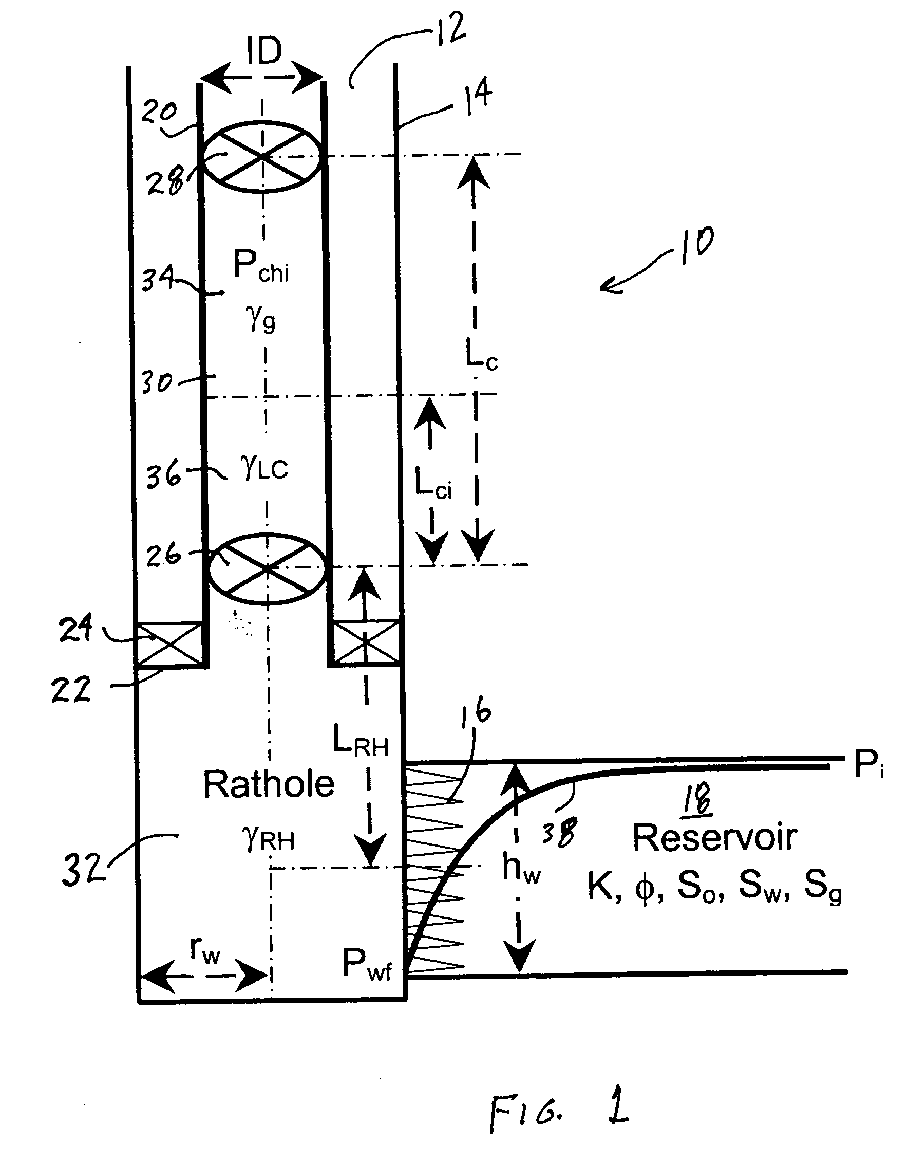
[0015]FIG. 1 provides an illustration, not to scale, of a model of a closed-chamber drillstem test system 10 and various parameters used in an embodiment of the present invention. The system 10 is shown positioned in a well 12, which in this embodiment includes a casing 14. Perforations 16 have been formed through casing 14 and into an earth formation 18 to permit production of fluids from the formation 18. The well 12 has be...


PUM


Abstract

A method for designing a closed-chamber drillstem test system. Parameters of available equipment and a well to be tested are collected. Initial or proposed chamber size and chamber pressurizing fluids are then selected. A simulation of a test is then performed. The simulation is performed in time increments, with pressure in the well assumed to be static during each time increment. Calculated flow volume from the formation during each increment is used to adjust pressure in the well for the next increment. The process is continued until the test would be considered complete based on an optimization parameter. If the total simulated time to complete the test is not in a desirable range, the initial chamber parameters are changed and the simulation is run again. The process is repeated until the simulated test time reaches a desirable range.

Description

CROSS-REFERENCE TO RELATED APPLICATIONS [0001] None. STATEMENT REGARDING FEDERALLY SPONSORED RESEARCH OR DEVELOPMENT [0002] Not applicable. REFERENCE TO A MICROFICHE APPENDIX [0003] Not applicable. FIELD OF THE INVENTION [0004] The present invention relates to testing hydrocarbon producing formations and more particularly to a method for designing a formation test system for use in a well. BACKGROUND OF THE INVENTION [0005] During drilling of oil and gas wells, it is desirable to test earth formations to determine their productive characteristics, e.g. how much oil and / or gas may be in the formation and how fast it can be produced. It is desirable to learn this information as soon as possible, e.g. before decisions are made to spend the money needed to complete a well for permanent production. One type of testing before completion is referred to as drillstem testing, since the primary work string available during drilling is the drillstring itself, although the equivalent testing ma...

Claims


Application Information

Patent Timeline
IPC IPC(8): G06F19/00
CPCE21B49/08
Inventor AZARI, MEHDI
Owner HALLIBURTON ENERGY SERVICES INC
Why Eureka
Try Eureka