Structure of gas sensor designed to minimize damage to porcelain insulators

a technology of gas sensor and porcelain insulator, which is applied in the direction of instruments, specific gravity measurement, machines/engines, etc., can solve the problems of many inherent defects of ceramic materials, and achieve the effect of reducing the concentration of local stress

Active Publication Date: 2006-09-28
DENSO CORP
View PDF5 Cites 10 Cited by
  • Summary
  • Abstract
  • Description
  • Claims
  • Application Information

AI Technical Summary

Benefits of technology

[0012] It is another object of the invention to provide an improved structure of a gas sensor which is designed to avoid breakage of porcelain insulators installed in a housing of the gas sensor According to one aspect of the invention, there is provided a gas sensor which may be installed in an exhaust system of an automotive internal combustion engine to measure the concentration of a selected component of emissions for use in burning control of the engine. The gas sensor comprises: (a) a hollow cylindrical housing; (b) a sensor element including a sensing portion and a base portion, the sensing portion working to produce a signal as a function of concentration of a target component of gases; (c) a first porcelain insulator having a top end surface and a base end surface opposed to the top end surface, the first porcelain insulator being installed in the housing and through and having the sensor element pass therethrough to expose the sensing portion to the gases outside the top end surface of the housing; a second porcelain insulator having a top end surface and a base end surface opposed to the top end surface, the second porcelain insulator being aligned with the first porcelain insulator in abutment of the top end surface thereof with the base end surface of the first porcelain insulator; and (e) a ground flat area formed on at least one of the base end surface of the first porcelain insulator and the top end surface of the second porcelain insulator to define an area of contact between the base end surface of the first porcelain insulator and the top end surface of the second porcelain insulator. Specifically, the base end surface of the first porcelain insulator and the top end surface of the second porcelain insulator are placed in abutment with each other through the ground flat surface. The base end surface of the first porcelain insulator and the top end surface of the second porcelain insulator, therefore, do not have micro-contacts therebetween, thereby minimizing the concentration of local stress on the base end surface of the first porcelain insulator and the top end surface of the second porcelain insulator to avoid breakage of the first porcelain insulator or the second porcelain insulator.
[0015] The ground flat area is so formed that an amplitude of an envelope curve defined by connecting peaks of undulations in a sequence of small zones to which a surface of the ground flat area is divided in unit of 0.5 mm in a selected direction lies within a range of 5 μm or less. This minimizes the concentration of local stress on the base end surface of the first porcelain insulator and the top end surface of the second porcelain insulator to avoid breakage of the first porcelain insulator or the second porcelain insulator.
[0016] The first porcelain insulator has a recess formed in the base end surface thereof. The second porcelain insulator has a protrusion formed on the top end surface thereof. The first and second porcelain insulators are placed in engagement of the recess in the base end surface of the first porcelain insulator with the protrusion on the top end surface of the second porcelain insulator. Specifically, the recess and the protrusion function as a positioning mechanism to ensure the alignment of the first and second porcelain insulators. The first and second porcelain insulators are made of ceramic material. The formation of the recess and protrusion, therefore, would result in a variation in grain density of the ceramic material around the recess and the protrusion during molding thereof. When burned or fired, the ceramic material is subjected to variation in local shrinkage due to the variation in density or quantity of heat the ceramic material undergoes, thus resulting in micro undulations on and many defects such as pore or micro cracks in the base end surface of the first porcelain insulator and the top end surface of the second porcelain insulator. This leads to a greater concern about the breakage occurring when the first and second porcelain insulators are subjected to physical loads. Accordingly, the formation of the ground area on the at least one of the base end surface of the first porcelain insulator and the top end surface of the second porcelain insulator is very useful for the structure of the gas sensor in which the recess is formed in the base end surface of the first porcelain insulator, and the protrusion is formed on the top end surface of the second porcelain insulator.

Problems solved by technology

The above structure, however, still has the problem in that within the contact area 93, the first and second porcelain insulators 91 and 92 are in abutment of curves surfaces of tops of the undulations to each other through which the first porcelain insulator 91 and the second porcelain insulator 92 receive the load from each other, which may result in the breakage thereof.
Usually, the ceramic material has many inherent defects such as pores or micro cracks in the surface thereof.

Method used


Image

  • Structure of gas sensor designed to minimize damage to porcelain insulators
  • Structure of gas sensor designed to minimize damage to porcelain insulators
  • Structure of gas sensor designed to minimize damage to porcelain insulators

Examples


Embodiment Construction

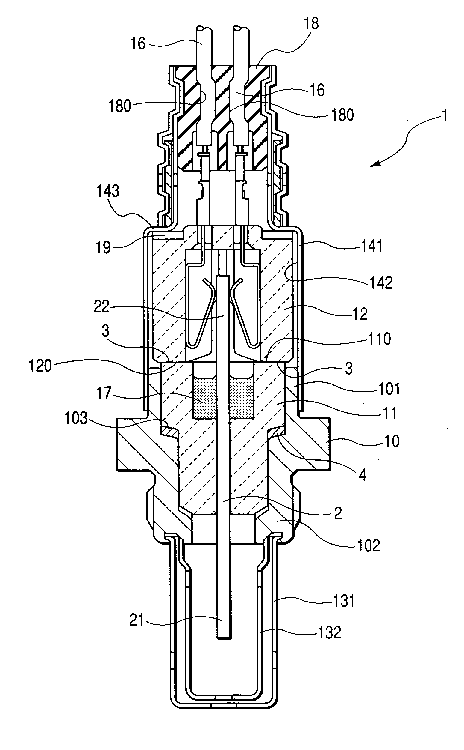
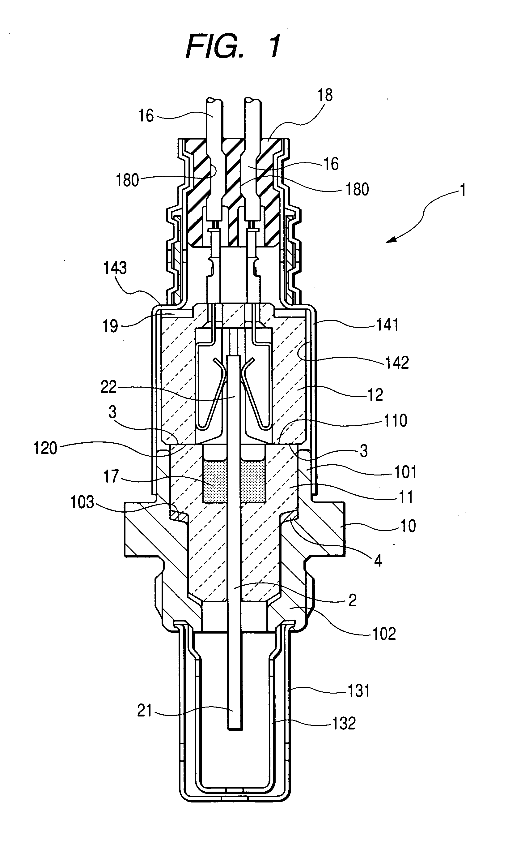
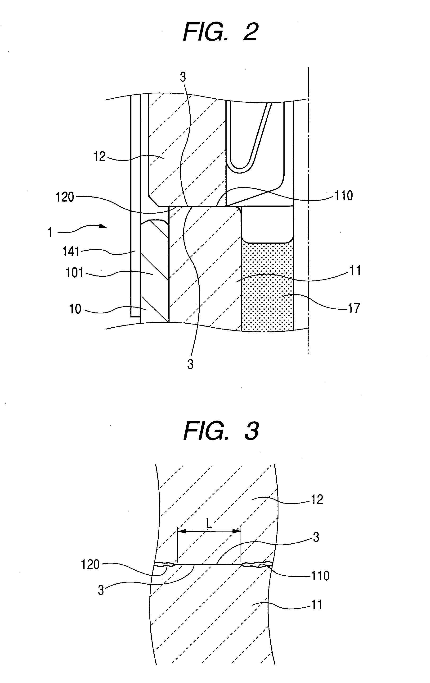
[0044] Referring to the drawings, wherein like reference numbers refer to like parts in several views, particularly to FIGS. 1 to 5, there is shown a gas sensor 1 according to the first embodiment of the invention which may be employed in a burning control system for automotive vehicles to measure concentrations of components such as NOx, CO, HC, and O2 contained in exhaust gasses of an internal combustion engine.

[0045] The gas sensor 1 will be described below, as an example, as being installed in an exhaust system of an automotive engine to measure the concentration of oxygen (O2) contained in emissions for use in burning control of the engine.

[0046] The gas sensor 1 generally includes a sensor element 2, a first hollow cylindrical porcelain insulator 11, a second hollow cylindrical porcelain insulator 12, and a hollow cylindrical housing 10, an air cover 141, and a protective cover assembly made up of outer and inner covers 131 and 132. The sensor element 2 is made of a laminate...


PUM

PropertyMeasurementUnit
distanceaaaaaaaaaa
diameteraaaaaaaaaa
diameteraaaaaaaaaa

Abstract

A gas sensor made up of a sensor element and a first and a second hollow cylindrical porcelain insulators covering the sensor element. The first porcelain insulator is laid on the second porcelain insulator in alignment within a body of the gas sensor. A base end surface of the first porcelain insulator is placed in abutment with a top end surface of the second porcelain insulator. At least one of the base end surface of the top end surface has a ground flat area which forms an interface between the first and second porcelain insulators without micro-contacts resulting in concentration of local stress which would lead to breakage of the first or second porcelain insulator when subjected to physical loads.

Description

CROSS REFERENCE TO RELATED DOCUMENT [0001] The present application claims the benefits of Japanese Patent Application No. 2005-83621 filed on Mar. 23, 2005 and Japanese Patent Application No. 2005-320941 filed on Nov. 4, 2005 disclosures of which are incorporated herein by reference. BACKGROUND OF THE INVENTION [0002] 1. Technical Field of the Invention [0003] The present invention relates generally to a gas sensor which may be installed in an exhaust system of an internal combustion engine for air-fuel ratio control, and more particularly to an improved structure of a gas sensor designed to ensure a desired mechanical strength of built-in porcelain insulators in withstanding applied physical loads. [0004] 2. Background Art [0005] Japanese patent First Publication No. 2001-343355 discloses a conventional gas sensor 9, as illustrated in FIG. 17, which is used in burning control of an internal combustion engine. The gas sensor 9 includes a housing 90, a first porcelain insulator 91, a...

Claims


Application Information

Patent Timeline
Patent Type & Authority Applications(United States)
IPC IPC(8): G01N7/00
CPCF01N11/00G01N27/4077
Inventor SATOU, YASUYUKIMAEDA, SEIJI
Owner DENSO CORP
Why Eureka
Try Eureka