Wear indicator for a tire

a technology of wear indicators and tires, applied in the direction of tires, vehicle components, non-skid devices, etc., can solve the problems of 25%, tire tread wear, tire tread wear, etc., and achieve the effect of small area

Active Publication Date: 2006-09-28
MICHELIN RECH & TECH SA
View PDF10 Cites 31 Cited by
  • Summary
  • Abstract
  • Description
  • Claims
  • Application Information

AI Technical Summary

Benefits of technology

[0013] The first objective of the present invention is to provide a tread comprising a simple wear indicator w

Problems solved by technology

Thus, a wear level of 25% means that the tread has lost a quarter of the rubber composition that can be worn away before changing (or retreading) becomes necessary.
As is known, the tread of a tire undergoes wear that results from the rolling of the tire.
If the tread has grooves, the effect of this wear is to reduce the depth of the grooves, thereby degrading the performance of the tire on wet ground.
On reaching a certain wear level, the tire no longer enables rolling to take place under optimum security conditions.
The wear level of a tread can be monitored by measuring the depth of the grooves, but that operation requires a suitable measurement tool, which makes it rather troublesome.
However, the use of colored rubber has a number of drawbacks, particularly relating to the complexity and cost of the fabrication process; exact positioning within the tread is difficult to ensure.
Moreover, inserts of colored rubber may give rise to irregular wear.
This approach is noted for its ease of implementation; but it has one major disadvantag

Method used


Image

  • Wear indicator for a tire
  • Wear indicator for a tire
  • Wear indicator for a tire

Examples


Embodiment Construction

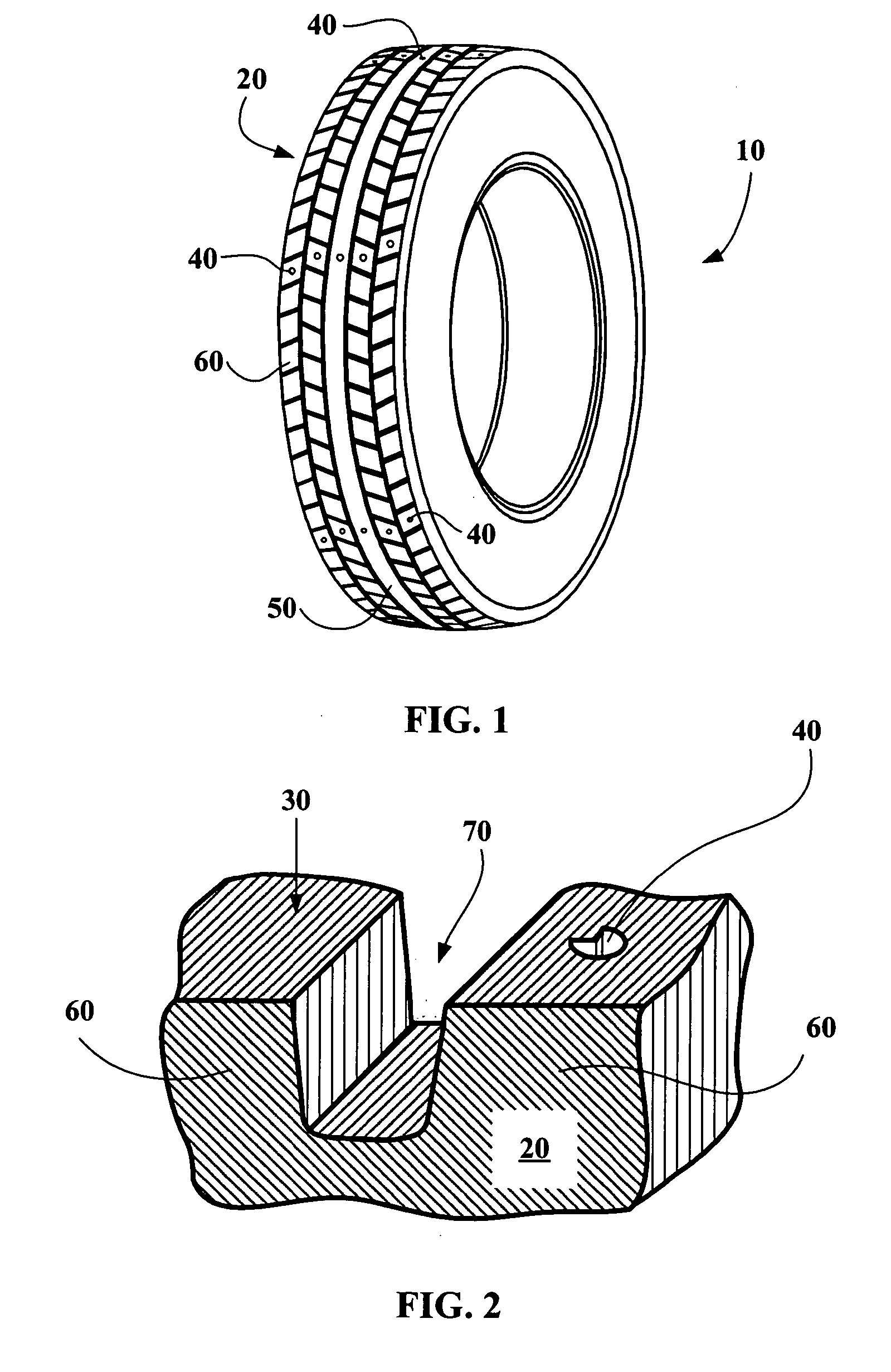
[0045]FIG. 1 is a schematic perspective view of a tire 10 whose tread 20 has a plurality of cavities 40 that serve as wear indicators. The cavities 40 are arranged across the full width of the rolling surface, both in the central rib 50 and in the tread elements 60 of the tread 20. It can also be seen that cavities 40 are arranged at several positions around the circumference of the tire.

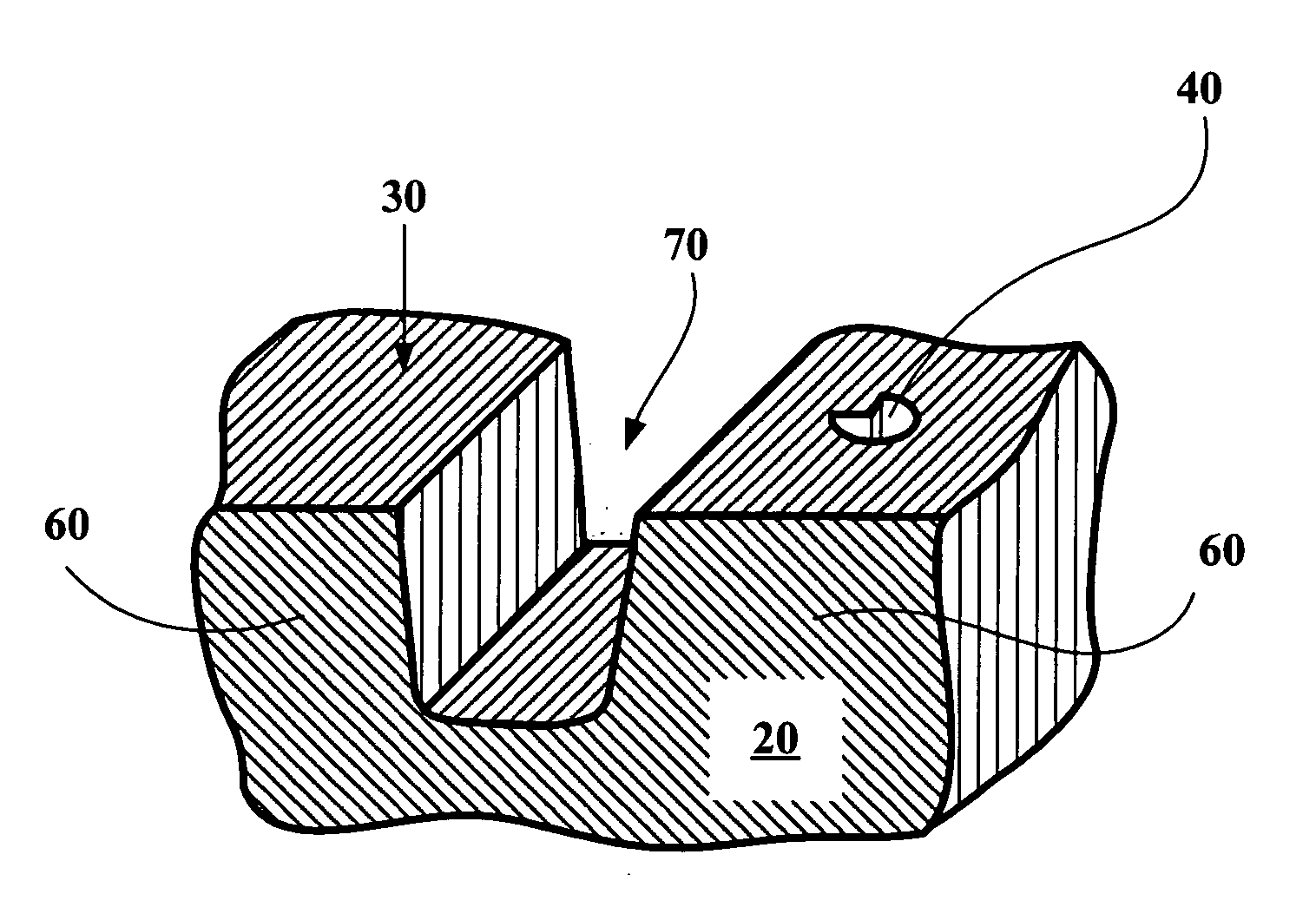
[0046]FIG. 2 is a schematic perspective view of part of a tread 20 according to the invention. The figure shows two tread elements 60 separated by a groove 70; on one tread element 60 a cavity 40 is provided in the rolling surface 30. The cavity 40 is of the same type as that represented in FIG. 6. In the example shown, the geometrical shape of the trace of the cavity 40 on the rolling surface 30 corresponds to a disc sector with an opening angle of 270°, corresponding to a tread wear level of 25%.

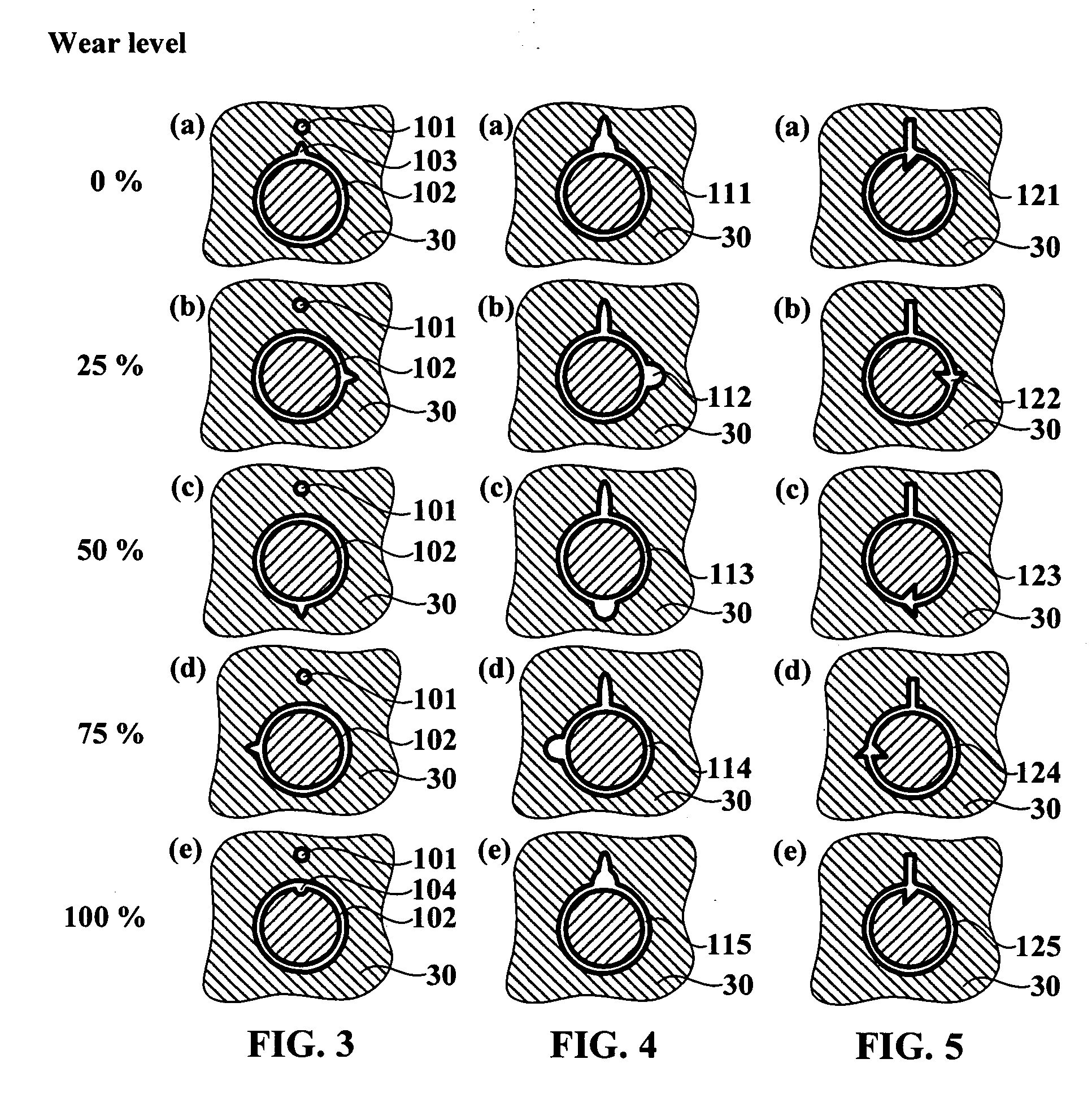
[0047]FIG. 3 is a schematic representation of the trace of a wear indicator according to the inventio...


PUM


Abstract

A tire tread comprising a rolling surface and at least one wear indicator formed by at least one cavity which opens onto the rolling surface, wherein the geometrical shape of the trace of the cavity on the rolling surface changes as a function of the wear level of the tread and wherein the geometrical shape of said trace is an analogical expression of the tread's wear level.

Description

FIELD OF THE INVENTION [0001] The present invention concerns tread wear indicators for tires. [0002] The “tread” of a tire is understood to mean a volume of rubber composition, delimited by two main surfaces one of which is intended to come into contact with the ground when the tire is rolling, and by lateral surfaces. [0003]“Rolling surface” means the surface formed by the points of a tire's tread that come into contact with the ground when the tire is rolling. [0004]“Wear level” of a tire tread means the ratio between the thickness that the tread has lost due to wear and the total thickness that the tread can lose before having to be changed or retreaded. Thus, a wear level of 25% means that the tread has lost a quarter of the rubber composition that can be worn away before changing (or retreading) becomes necessary. The wear level is generally expressed as a percentage; at a given moment not all the zones of the tread necessarily have the same wear level (“uneven wear”). [0005] H...

Claims


Application Information

Patent Timeline
IPC IPC(8): B60C11/24B60C11/02
CPCB60C11/24Y10T152/10027Y10S152/03
Inventor KEMP, PRESTON BUTLERFOUCHER, BENOIT
Owner MICHELIN RECH & TECH SA
Why Eureka
Try Eureka