Radiator core support structure and its assembly method

a technology of supporting structure and radiator, which is applied in the direction of vehicle components, propulsion parts, lighting and heating apparatus, etc., can solve the problems of large gaps that are unavoidable, and achieve the effect of reducing impact and easy sliding

Inactive Publication Date: 2006-09-28
CALSONIC KANSEI CORP
View PDF1 Cites 32 Cited by
  • Summary
  • Abstract
  • Description
  • Claims
  • Application Information

AI Technical Summary

Benefits of technology

[0043] Therefore, the heat exchanger can be easily slidable in its assembly and elastically mountable for decreasing impact caused from vehicle running.

Problems solved by technology

However, the conventional radiator core support structure has disadvantages in that large gaps ◯ are unavoidable between the pipes 03 and 04 and the radiator core support 02 respectively, as shown in FIGS. 10C and 11 when the heat exchanger 01 and the core support 02 are assembled with each other, since they are elongate holes.

Method used


Image

  • Radiator core support structure and its assembly method
  • Radiator core support structure and its assembly method
  • Radiator core support structure and its assembly method

Examples


first embodiment

[0057] A radiator core support structure of a first embodiment according to the present invention will be described with reference to the accompanying drawings. In this description, the terms “right”, “left”, “front”, “rear”, “forward” and “rearward” are those identified with respect to a vehicle body, not to those in the drawings.

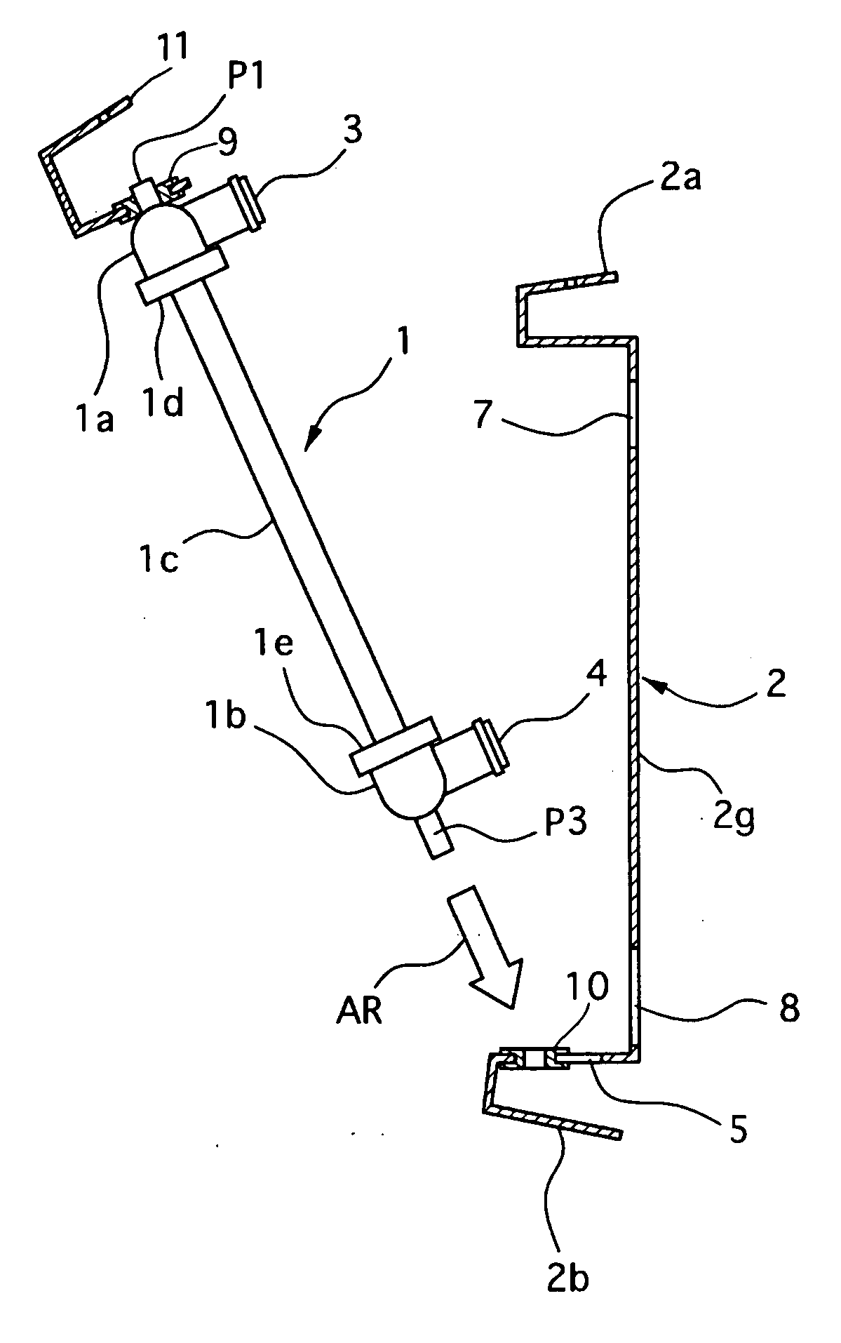
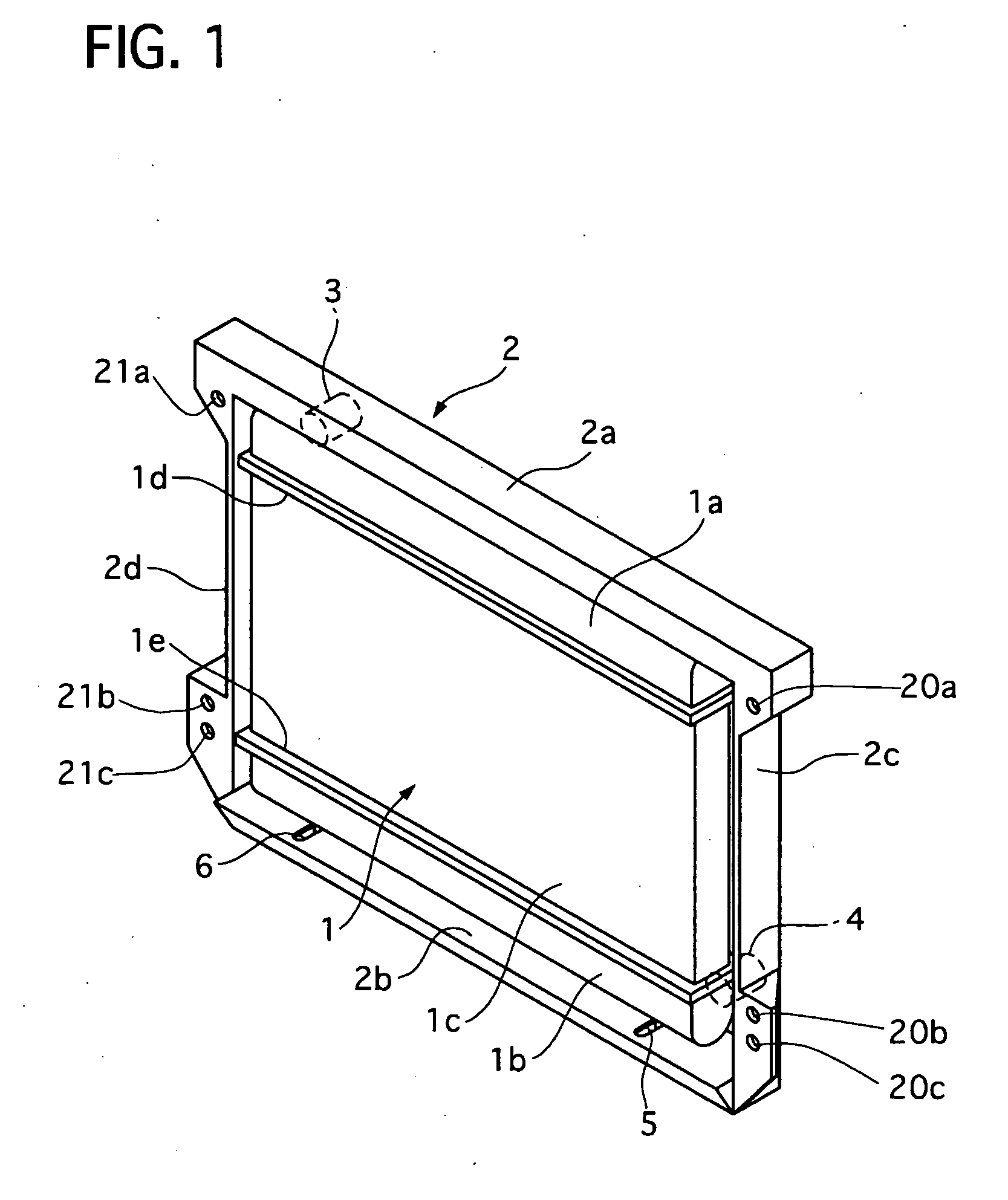
[0058] Referring to FIGS. 1 to 3, the radiator core support structure are fixed to a front part of the vehicle body, not shown, and defines an engine room together with the vehicle body. The radiator core support structure includes a radiator 1 and a radiator core support 2. The radiator 1 acts as a heat exchanger of the present invention.

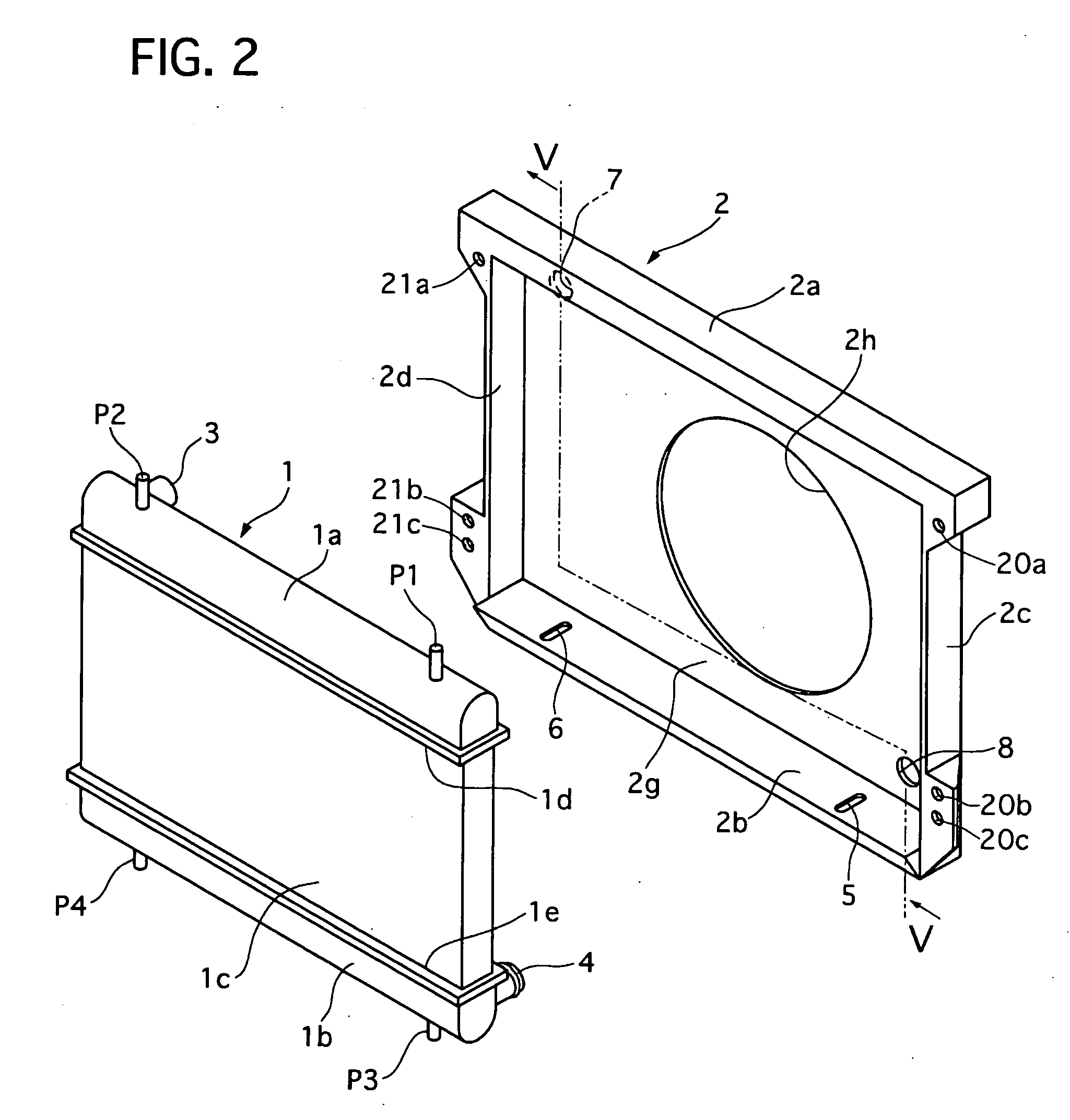
[0059] The radiator 1 comprises an upper tank 1a, a lower tank 1b arranged in parallel with and under the upper tank 1a, a radiator core 1c arranged between the upper and lower tanks 1a and 1b.

[0060] The upper tank 1a is provided on its top portion with an upper left mounting pin P1 and an upper right mounting pin P2, w...

second embodiment

[0094] Next, a radiator core support structure of a second embodiment will be described with reference to the accompanying drawing of FIG. 9.

[0095] The radiator core structure of the second embodiment includes a radiator 1 and a radiator core support 2. The radiator core support 2 has a lower portion 2b formed with a lower left fixing hole 5 and a lower right hole 6′, which are apart from each other in a lateral direction of the radiator core support 2.

[0096] The lower left fixing hole 5 is formed to be an elongate hole extending forward for allowing a lower left mounting pin P3 to slide along it.

[0097] The lower left hole 6′ is formed to be a round hole with a diameter slightly larger than that of the lower right pin P4. The lower left hole 6′ acts as a slide-preventing hole of the present invention.

[0098] The other parts of the radiator core support structure of the second embodiment are similar to those of the first embodiment.

[0099] In this embodiment, the lower left pin P3 ...


PUM


Abstract

A radiator core support structure comprises a radiator core support and a heat exchanger. The former has a through-hole, and a fixing hole on its the lower portion. The latter has a pipe projecting rearward and introduceable in the through-hole and a lower mounting pin projecting downward from its bottom portion. The fixing hole is formed as an elongate hole extending toward the front side so that the pipe can be kept free from an interference between the pipe and the radiator core support when the lower mounting pin is inserted in a front side of the fixing hole and the heat exchanger is turned rearward around the front side of the fixing hole to stand erect. Then, the fixing hole allows the mounting pin to be slid rearward for introducing the pipe through the through-hole.

Description

BACKGROUND OF THE INVENTION [0001] 1. Field of the Invention [0002] The present invention relates to a radiator core support structure, and in particular to the radiator core support structure in which a radiator core support supports a heat exchanger whose pipes are introduced through through-holes formed on the radiator core support. This invention also relates to a radiator core support structure assembly method in which the radiator and the radiator core support are assembled with each other. [0003] 2. Description of the Related Art [0004] In recent years, various reviews for downsizing an engine room of a motor vehicle have been made for the purpose of obtaining a larger space of a passenger compartment. The reviews have been carried out on components in the engine room, such as an engine, auxiliary machines, and a radiator core support which acts as a carrier of a heat exchanger, and also on a layout of them. One attempt solution is to improve a radiator core support structure...

Claims


Application Information

Patent Timeline
Patent Type & Authority Applications(United States)
IPC IPC(8): F28F9/007
CPCB60K11/04F28D2021/0096F28F9/002
Inventor KOBAYASHI, HIDEKIMASHIO, KATSUJIHARA, KENJITSUMURA, KOJIMORI, EIICHIOKAMOTO, KOSUKE
Owner CALSONIC KANSEI CORP
Why Eureka
Try Eureka