Variable hand switch
a variable hand switch and air pressure technology, applied in the field of variable hand switches, can solve the problems of difficult accurate control of the apparatus itself, serious accidents, and difficulty in operation of variable hand switches utilizing the high/low air pressure described above, so as to improve operability, reliably operate, and reduce the effect of pressing for
- Summary
- Abstract
- Description
- Claims
- Application Information
AI Technical Summary
Benefits of technology
Problems solved by technology
Method used
Image
Examples
first embodiment
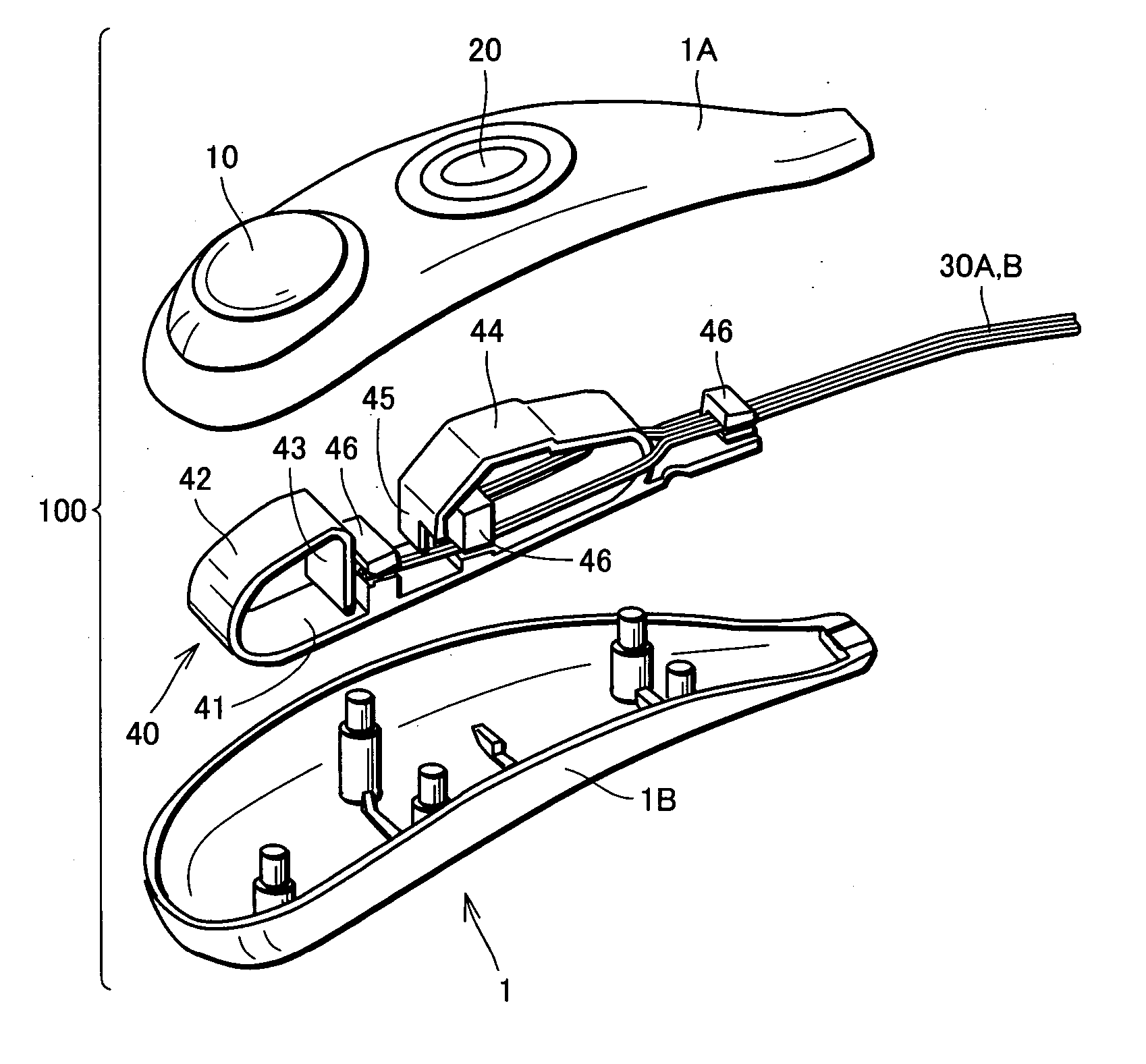
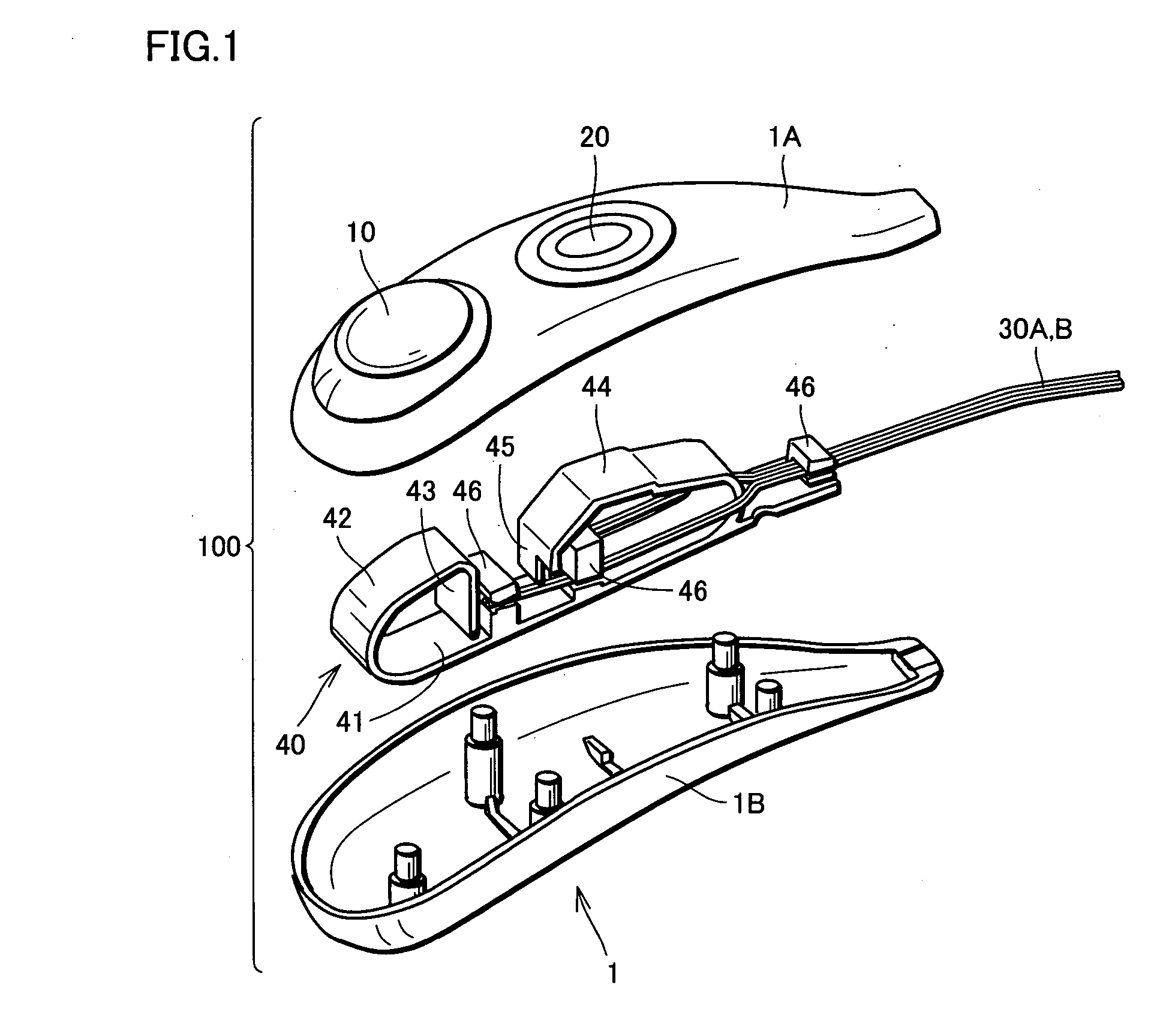
[0034] First, referring to FIGS. 1 and 2, an appearance of a variable hand switch in accordance with the first embodiment will be described. FIG. 1 is an entire exploded perspective view showing overall structure and inner structure of the variable hand switch 100, and FIG. 2 shows variable hand switch 100 held by one hand.
[0035] (Appearance of Variable Hand Switch 100)
[0036] Variable hand switch 100 is intended to be held by a hand, and therefore, it has a longitudinal housing case 1 having a curved shape fit for good holding. Housing case 1 has a structure divided into two, including a first case 1A and a second case 1B. Between the first and second cases 1A and 1B, an area allowing attachment / detachment of these cases is provided.
[0037] On an upper surface of first cast 1A, a first switch 10 having an approximately curved shape formed of an elastic member (silicone rubber or the like) serving as a switch, and a second switch 20 having an approximately curved shape formed of an...
second embodiment
[0057] A second embodiment of variable hand switch 100A will be described with reference to FIGS. 9 to 11. FIG. 9 is an overall perspective view showing an appearance of variable hand switch 100 in accordance with the present invention, and FIGS. 10 and 11 are first and second schematic illustrations representing the principle of operation of variable hand switch 100A in accordance with the present embodiment.
[0058] By way of example, assume that variable hand switch 100A is applied for controlling the amount of introducing contrast medium of an injector head. An operator may wish to know the injection pressure of the contrast medium or the like to the patient. In such a case, an arrangement of variable hand switch 100A with an air bag 80 may be used.
[0059] Referring to FIG. 10, the injection pressure of the contrast medium to a patient is detected by an injection pressure measuring apparatus 152, through a plunger 153 in a syringe 151. Therefore, based on the information detected...
third embodiment
[0060] Next, a variable hand switch 200 in accordance with the third embodiment will be described with reference to FIGS. 12 to 14. FIG. 12 is an enlarged partial cross section showing an internal structure of variable hand switch 200, FIG. 13 is a cross section taken along the line XIII-XIII of FIG. 12, and FIG. 14 is a partial perspective view representing another internal structure of variable hand switch of the present embodiment. It is noted that the basic structure of variable hand switch 200 in accordance with the present embodiment is the same as the structure of the first and second embodiments, and therefore, the same or corresponding portions are denoted by the same reference characters and description thereof will not be repeated. Only the characteristic structural portions will be described in detail in the following.
[0061] In variable hand switches 100 and 100A shown in the first and second embodiments, the amount of control is adjusted by measuring light reflectance ...
PUM
 Abstract
Description
Claims
Application Information
 - R&D
- Intellectual Property
- Life Sciences
- Materials
- Tech Scout
- Unparalleled Data Quality
- Higher Quality Content
- 60% Fewer Hallucinations
Browse by: Latest US Patents, China's latest patents, Technical Efficacy Thesaurus, Application Domain, Technology Topic, Popular Technical Reports.
© 2025 PatSnap. All rights reserved.Legal|Privacy policy|Modern Slavery Act Transparency Statement|Sitemap|About US| Contact US: help@patsnap.com


