One significant limitation of conventional claw hammers is that they cannot be used to extract nails easily or quickly.
In particular, as the nail is extracted using the conventional claw hammer, the fulcrum point moves away from the nail, thereby effectively decreasing the leverage and effectively increasing the required force that must be exerted by the user of the hammer to further extract the nail.
This
disadvantage or limitation of the conventional claw hammer is especially problematic when the nails are designed to be difficult to extract.
For instance, large nails, glue-coated nails, or nails having ribbed shanks may be very difficult to extract and may therefore require
exertion of substantial force by the user to do so.
Other limitations of the conventional claw hammer relate to the extraction of relatively
long nails, or nails that have already been partially removed from a surface.
Due to the geometry of the conventional claw in relation to the striking portion of the hammer head, complete extraction is often impeded.
In addition, if the nail to be extracted is especially long, extraction using a conventional claw may also severely bend the nail so that complete extraction is further impeded.
The proposed solutions, however, utilize various
moving parts that increase the cost and decrease the durability of the hammers.
In addition, in many proposed implementations, the hammers must be manually adjusted to provide for the extended fulcrum, which makes the use of the hammers with such features cumbersome, inconvenient, and time-consuming.
A moveable, extensible fulcrum also decreases the stability of the hammers, and along with the wear and breakage of the fulcrum mechanism inevitably occasioned by the conventional striking and ripping uses of the hammers, creates a substantial risk of injury to the user.
Such proposed claw hammers, however, still fail to address the leverage limitation caused by the movement of the fulcrum away from the nail.
The various proposed solutions fail to solve the inefficiencies associated with extraction by conventional means, and in turn create separate problems that engender either additional inefficiencies, such as breakage,
instability, time waste, exhaustion, and potential injury, or various interferences with the full functioning of the conventional claw hammer.
Still another limitation of the conventional claw hammer is that due to the positioning of the claw on the hammer head, the user must reverse his grip and / or turn the hammer around to use the claw.
This impedes work efficiency in situations where nails must be driven and extracted quickly on a continuous basis.
For instance, weaker nails such as aluminum,
brass, or galvanized nails tend to bend when being driven into harder woods or surfaces.
The lathing hatchet of the '903 reference cannot be used like a conventional hammer, however, because a claw is not provided opposite to the hammer poll.
Moreover, the claw of the disclosed lathing hatchet fails to provide sufficient leverage to accomplish efficient or complete extraction of most nails.
In particular,
long nails and nails that extend from a surface at various lengths cannot be easily extracted using the disclosed lathing hatchet.
In this regard, the disclosed lathing hatchet admits of inefficiencies similar to those inherent in the proposed solutions to the problems associated with using the conventional claw hammer as a nail extractor.
The use of this holding feature is cumbersome, however, because it requires tightening and loosening of the
set screw each time the user desires to use the holding feature.
Therefore, in view of the above, an unfulfilled need still exists for an improved hammer that avoids the above described limitations of the conventional and prior art hammers.


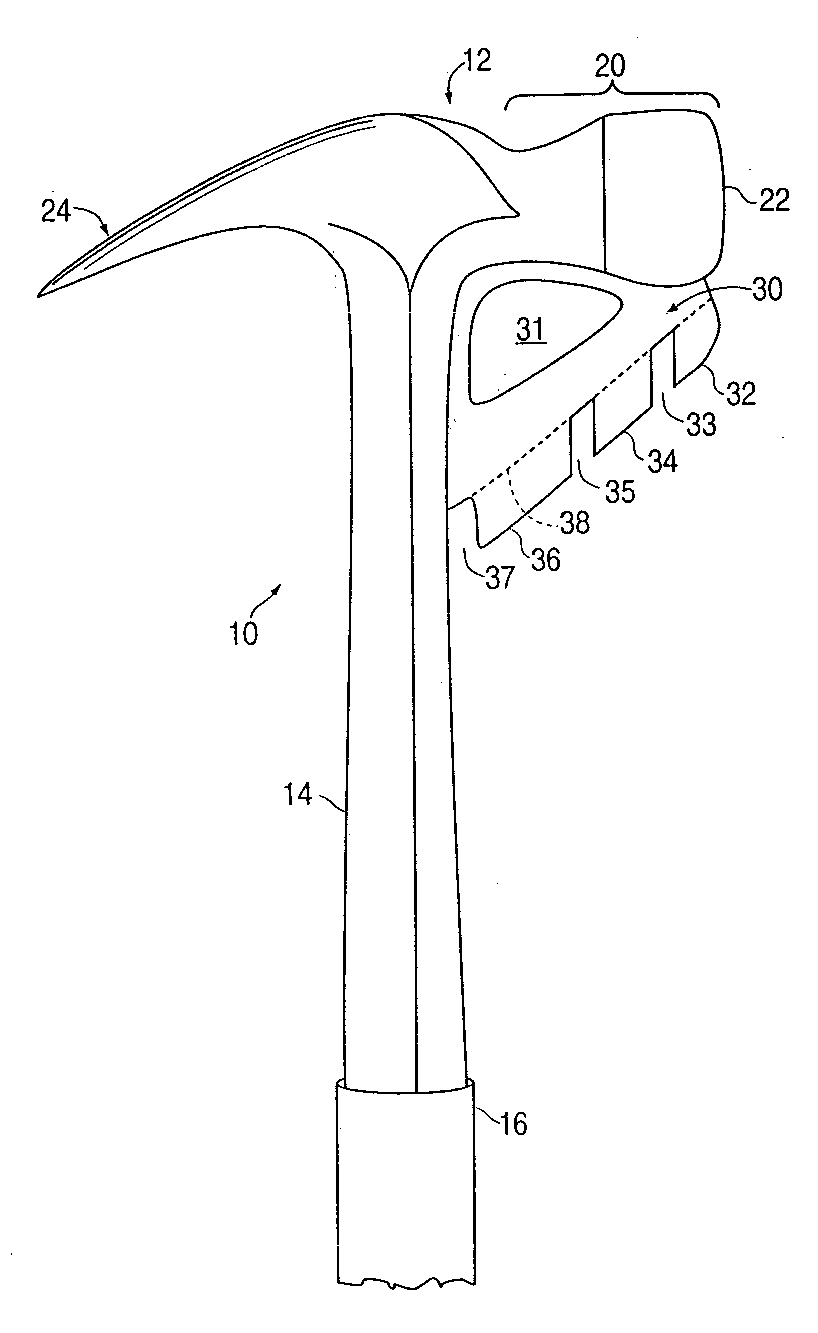
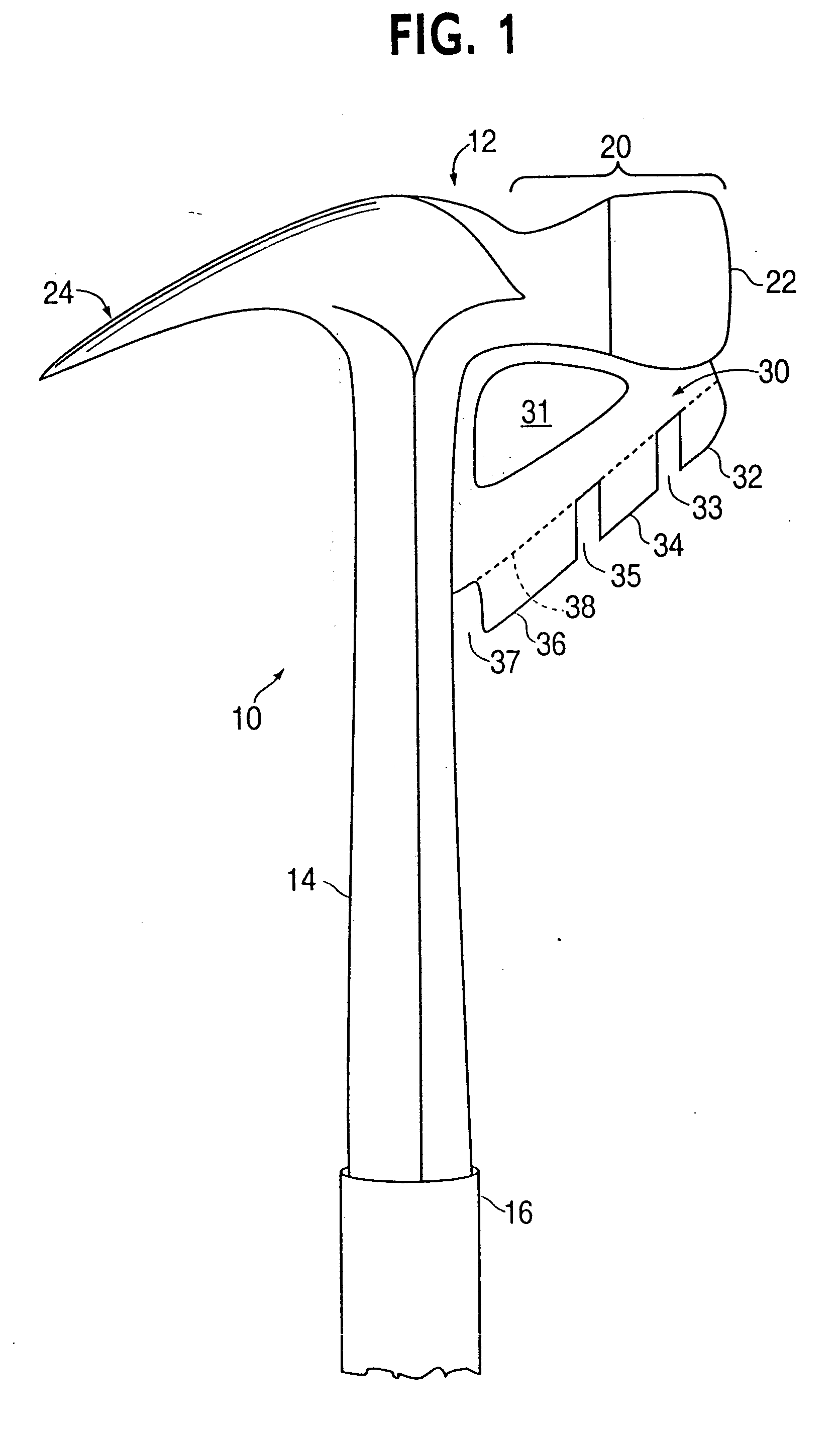
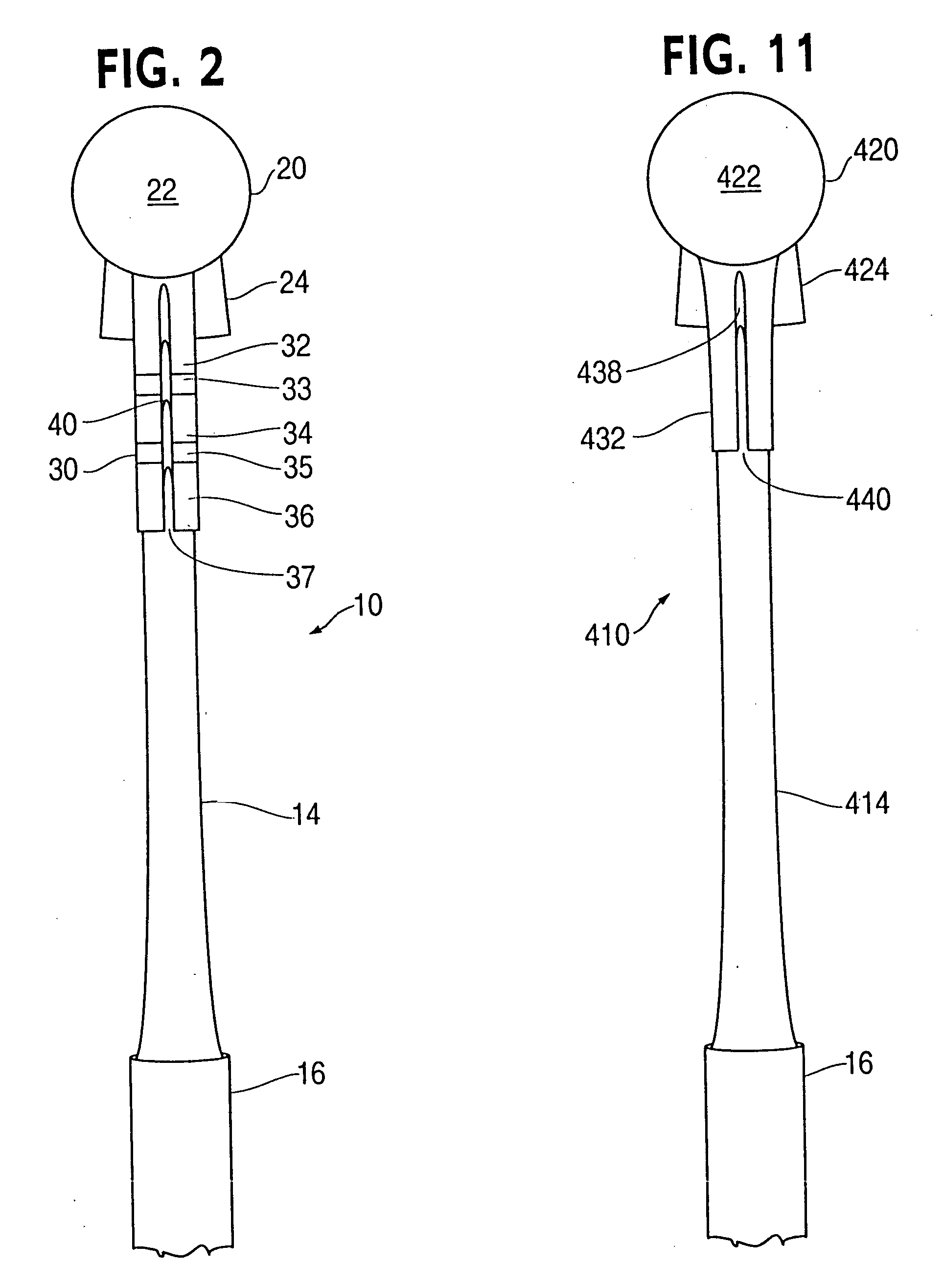