Radio frequency tag and method for regulating the same

Inactive Publication Date: 2006-09-28
TOSHIBA TEC KK
View PDF14 Cites 145 Cited by
  • Summary
  • Abstract
  • Description
  • Claims
  • Application Information

AI Technical Summary

Benefits of technology

[0009] Accordingly, it is an object of the present invention to easily regulate the l

Problems solved by technology

An amount of such inputted signal reflected and returned may be increased due to failure to the impedance matching.
However, it is rather difficult to alter or change various constants and/or

Method used


Image

  • Radio frequency tag and method for regulating the same
  • Radio frequency tag and method for regulating the same
  • Radio frequency tag and method for regulating the same

Examples


Example

[0022] A first embodiment of the present invention will be described with reference to FIG. 1. FIG. 1 shows a block diagram illustrating the construction of an RF tag data read-out system using an RF tag 1 and an interrogator 3.

[0023] The RF tag 1 is constituted with an IC chip 11 and a dipole antenna 13 electrically connected to the IC chip 11 to receive or radiate radio waves from the antenna 13. The IC chip 11 includes a communication control section 15 that controls the communication operation and a memory section 17 that stores several data.

[0024] The interrogator 3 includes an antenna 31, a transmission / reception section 33 which carries out the transmission / reception operation and a control section 35 which controls the operation of the transmission / reception section 33. The transmission / reception section 33 is mechanically and electrically connected to the antenna 31 through a coaxial cable 37. The antenna 31 performs the transmission / reception of radio waves from or to th...

Example

Second Embodiment

[0046] As shown in FIG. 4, a plurality of document files (article) 41 is housed in a container 43. An RF tag 45 is attached to the lower side of each file 41 and each RF tag 45 has a memory that stores a unique ID data different from other RF tags. The plurality of document files 41 each having RF tag 45 are contained in the container 43 such that the RF tags 45 of the files 41 are located nearest to the bottom of the container 43.

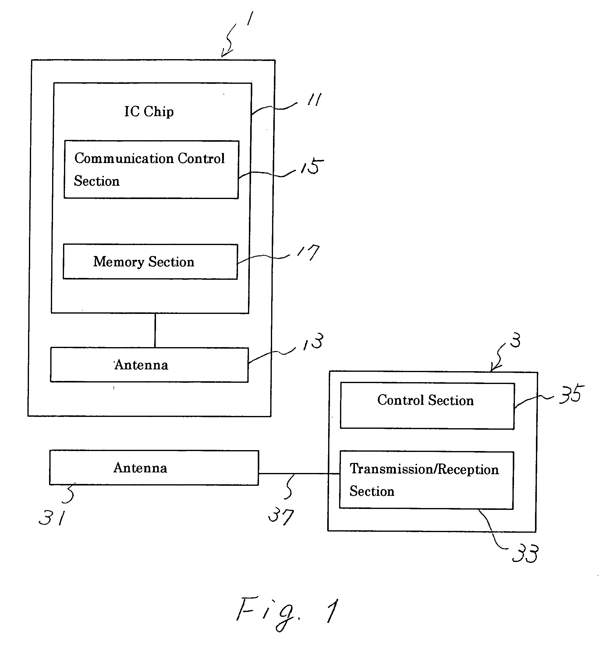
[0047] When making the container 43 in which the plurality of files 41 have been housed approach the antenna 31 of the interrogator 3, a radio communication between the antenna 31 and the antenna of each RF tag 45 is executed and the interrogator 3 reads out the unique ID data from the memory of each RF tag 45 to manage the plurality of files 41 in the container 43. The antenna 31 of the interrogator 3 has a characteristic that the radio waves from the antenna 31 are intensively radiated toward the bottom of the container 43 in FIG. 4.

[...

Example

Third Embodiment

[0054] Another modification of the RF tag will also be described hereinafter.

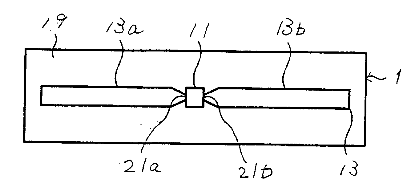
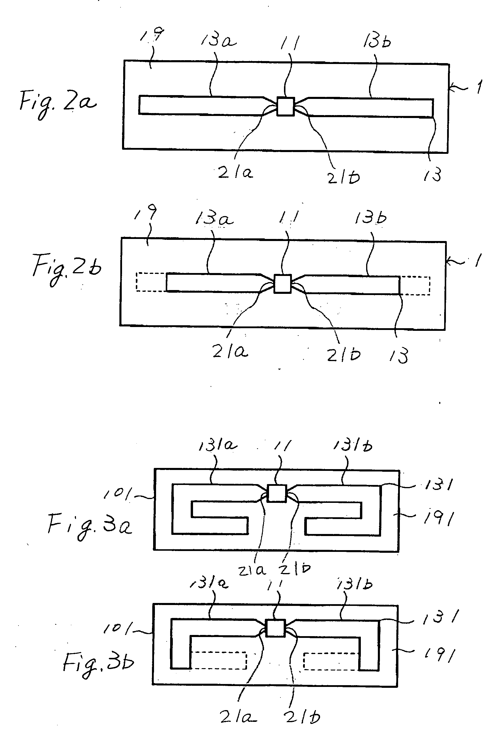
[0055] As shown in FIG. 6, a plurality of marks 47 (dotted line) acting as an indicator are printed on the dielectric base 19 such that the marks 47 are located orthogonal to and along the respective patterns 13a and 13b and each location of corresponding marks 47 along the respective patterns 13a and 13b is an equally distance from the respective feed points 21a, 21b of the IC chip 11.

[0056] When applying the RF tag 45 shown in FIG. 6 to an article, such as a document file, length of the antenna patterns 13a and 13b is regulated to be matched with the wave-length of radio waves traveling through the article such that it is eliminated at a location of marks 47. The elimination operation is easily carried out using the plurality of marks 47 and each length of the antenna patterns 13a and 13b can be equally eliminated at the corresponding marks 47.

[0057] In the above-described embodiment, ...


PUM


Abstract

An RF tag includes an IC chip and a dipole antenna both arranged on a dielectric base. The dipole antenna is composed of a pair of antenna patterns each of which is connected to respective feed points of the IC chip and extends in an opposite direction. When manufacturing the RF tag, length of the pair of antenna patterns is set so that the impedance matching between the IC chip and the dipole antenna is optimum in the air. When using the RF tag attached on an article, the extending ends of the antenna patterns are eliminated so that the length of the dipole antenna matches the wave-length of radio waves traveling through the article that the RF tag is attached.

Description

BACKGROUND OF THE INVENTION [0001] 1. Field of the Invention [0002] This invention relates, in general, to a radio frequency transponder, such as an RFID (radio frequency identification) tag. In particular, the invention relates to an RFID tag including an IC chip and a dipole antenna arranged on a dielectric base and a method for regulating the length of the dipole antenna of the RFID tag when using the tag attached to a specific article. [0003] 2. Description of the Related Art [0004] It becomes necessary to employ an apparatus exclusively designed to manufacture an RFID tag (hereinafter referred to as RF tag) which includes an IC chip having a radio communication section and a memory section and an antenna, as the IC chip is minutualized. [0005] A method for manufacturing such RF tag may be that an antenna pattern is printed on a base and thereafter an IC chip is connected with the antenna pattern. Another method may be that an antenna pattern is printed after an IC chip is mount...

Claims


Application Information

Patent Timeline
IPC IPC(8): G08B13/14
CPCG06K19/07749G08B13/2417H01Q1/22H01Q9/26H01Q9/28H01Q19/005
Inventor MUROFUSHI, NOBUOSANO, KOUICHIKIJI, YASUHITO
Owner TOSHIBA TEC KK
Why Eureka
Try Eureka