Method, device and program storage medium for controlling communication

a communication and program storage technology, applied in the field of communication control devices, can solve problems such as increased packet loss, deterioration of ip-san input/output performance, and increased loss or rtt of packets on the ip network

Inactive Publication Date: 2006-09-28
HITACHI LTD
View PDF9 Cites 15 Cited by
  • Summary
  • Abstract
  • Description
  • Claims
  • Application Information

AI Technical Summary

Benefits of technology

[0043] With the above method, device and program storage medium, a single device can be connected appropriately to multiple hosts under various conditions such as communication distance or quality.

Problems solved by technology

However, compared to communications according to FC, communications of IP are more likely to cause packet losses during communications.
This may deteriorate the input / output performance of IP-SAN greatly.
However, the losses or RTT of packets may be increased on the IP network.
If this receiver receives the TCP packets on the network in which frequent packet losses and long RTT occur, then the time period during which all the TCP packets are received ends up being long.
As a result, the start of the protocol process delays.
Excessively long delay may be regarded as abnormal (any error has occured).
Conditions required for systems of IP-SAN, such as servers or storages, are complex, compared to those of FC-SAN.
If the performance of a server is low, then the performance of the communications is not enhanced at all, even when a high-spec storage is used.
However, at present, the iSCSI storage technique does not sufficiently allow for optimization of communications when a large number of hosts or a wide variety of networks are used.
However, neither of the above techniques allow for the case where a device communicates with multiple partners of different communication statuses at the same time.
In other words, these techniques do not support to optimize a communication per session.
This becomes a problem.
Furthermore, IP storage systems may have a relatively small number of ports.
This becomes an additional problem.

Method used


Image

  • Method, device and program storage medium for controlling communication
  • Method, device and program storage medium for controlling communication
  • Method, device and program storage medium for controlling communication

Examples


first embodiment

[0071] In a first embodiment of the present invention, at least one network port through which a communication is controlled per session is provided.

[System Configuration]

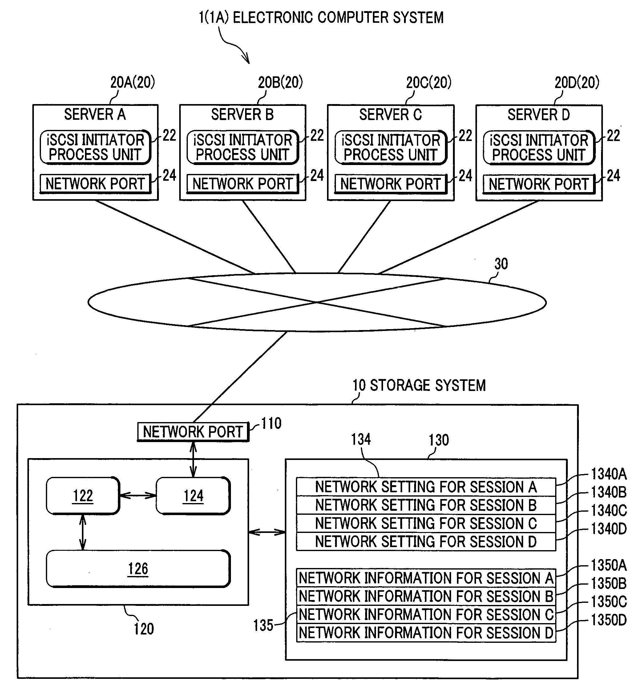
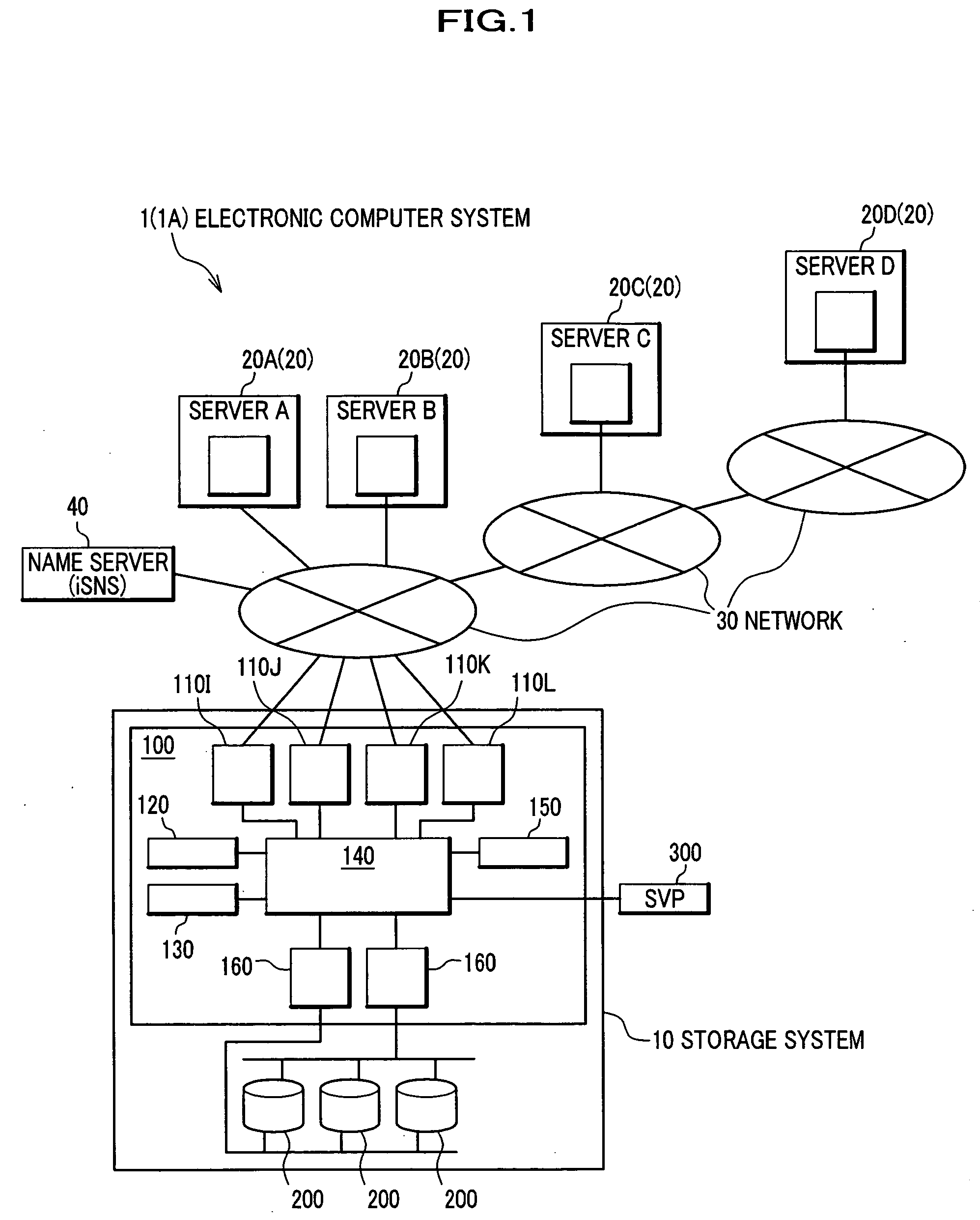
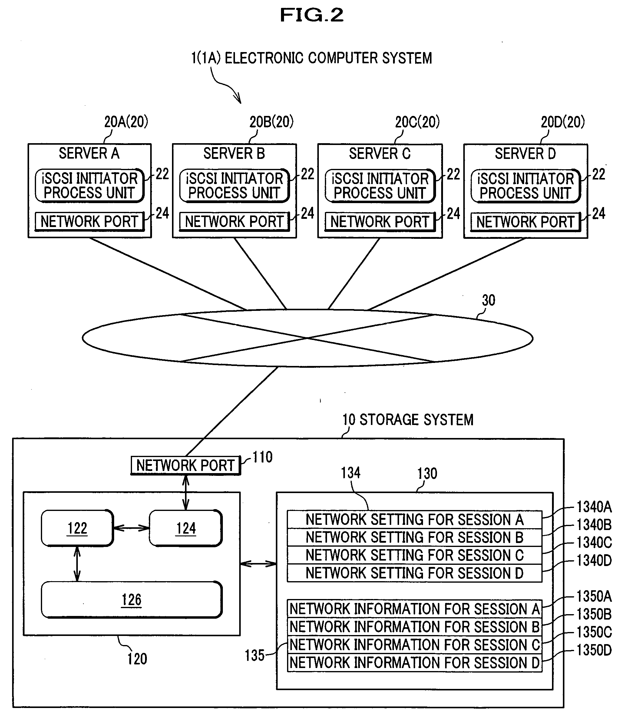
[0072] Referring to FIG. 1, an electronic computer system 1 (1A) includes a storage system 10, servers 20 (servers 20A, 20B, 20C and 20D), and a name server 40 which are all connected to a network 30. In this system, packet-formatted data is sent / received between the storage system 10 and the servers 20 through the network 30. The server 20 writes / reads data to or from the storage system 10 by using a write / read command of SCSI that is an upper layer protocol of iSCSI.

[0073] The storage system 10 includes a storage controller 100, memory units 200, and a service processor (SVP) 300. Each memory unit 200 is a disk drive device to which data is written by a host.

[0074] The storage controller 100 is provided with network ports 110I, 110J, 110K and 110L. Typically, these network ports each have a physical port to b...

second embodiment

[0121] Referring to FIG. 14, a system of this embodiment fundamentally has a similar configuration to that of the first embodiment. The system of this embodiment includes a group-unit network setting table 136 and a session-unit network information table 137 in a control memory 130. Since other components are similar to those of the first embodiment, a description thereof will be omitted.

[System Configuration]

[0122] The system of the first embodiment controls network setting per session. In contrast, this system forms some groups in advance each of which is composed of sessions, and handles the group as a unit of network setting. Therefore, the same network setting is applied to the sessions in one group, and the network settings of sessions in different groups differ from one another. A detail description thereof will be given later.

[0123] To group the sessions, an administrator defines beforehand, by using a SVP, the ranges of the RTT and error occurrence rate which are allowed...

third embodiment

[0131] A storage system 10 of a third embodiment has multiple ports and utilizes a function of an iSCSI name server. However, since other components and communication processes are similar to those of the first embodiment, a description of similar portions will be omitted.

[System Configuration]

[0132] A typical storage system has multiple physical ports, and in this embodiment, network parameters are allocated to such ports. All the ports can log in to the same iSCSI target. Once a session is established, the storage system 10 monitors the RTT and the packet error rate of this session, and re-directs a connection to a physical port suitable for the session. The above monitor and re-direction are performed by a communication management unit 124. This re-direction is executed with an iSCSI name server function of an ISNS name server 40. A detail description thereof will be given later with reference to FIGS. 22 and 23.

[0133] The re-direction is controlled based on the port-unit netw...


PUM


Abstract

Disclosed is a communication control method which enables a single device to be connected appropriately to multiple hosts under various conditions. The method, which is executed by a storage system composed of a processing unit, a storage unit and a connecting unit for a network, includes the steps of receiving a request for a communication from the network by the connecting unit, determining at least one characteristic of the communication by the processing unit, storing the determined characteristic and a threshold of the characteristic in the storage unit, conducting an analysis of the characteristic by the processing unit, while referring to the threshold, specifying at least one parameter of a communication protocol based on a result of the analysis by the processing unit, and performing the communication in accordance with the specified parameter by the connecting unit.

Description

CROSS-REFERENCE TO RELATED APPLICATIONS [0001] This application claims the benefit of Japanese Patent Application 2005-083167 filed on Mar. 23, 2005, the disclosure of which is incorporated herein by reference. BACKGROUND OF THE INVENTION [0002] 1. Field of the Invention [0003] The present invention relates to a method and a device for controlling communications upon access to storages. Furthermore, the present invention relates to a medium that stores a program for executing the above method. [0004] 2. Description of the Related Art [0005] Conventionally, communications between a server (or host) and a storage device have been performed in accordance with Fibre Channel (FC), and the server and the storage have mainly been connected through a specific network. Such a network is called “storage area network (SAN)”. Especially, SAN that employs FC as a network control protocol is called “FC-SAN”. In FC-SAN, a small computer system interface (SCSI) or a single byte command code set (SB...

Claims


Application Information

Patent Timeline
Patent Type & Authority Applications(United States)
IPC IPC(8): H04L12/56H04L29/06
CPCH04L47/10H04L47/283H04L47/323H04L67/1097
Inventor SHIROGANE, TETSUYA
Owner HITACHI LTD
Why Eureka
Try Eureka