
Apparatus for producing sound effect for mobile object

a mobile object and sound effect technology, applied in the direction of electrical transducers, gain control, instruments, etc., can solve the problems of loss of linearity, unattractive performance level of the conventional sound effect producing apparatus, and prone to sound effect interruptions, so as to improve the linearity of the sound effect and reduce the interruption of the sound effect. , the effect of excellent acoustic

Inactive Publication Date: 2006-09-28
HONDA MOTOR CO LTD
View PDF4 Cites 51 Cited by
  • Summary
  • Abstract
  • Description
  • Claims
  • Application Information

AI Technical Summary

Benefits of technology

[0008] It is therefore an object of the present invention to provide a mobile object sound effect producing apparatus which is capable of achieving an excellent acoustic effect within a sound field when a sound effect is produced in the sound field, by increasing the linearity of the sound effect and reducing sound effect interruptions, which would otherwise occur due to peaks and dips of the responses of acoustic characteristics of the sound field (also referred to as sound field characteristics), in view of the acoustic characteristics of the sound field.
[0009] Another object of the present invention is to provide a mobile object sound effect producing apparatus, which is capable of preventing large sound effects from being produced when the engine on the mobile object is raced, or when the transmission on the mobile object has a throttle kickdown.

Problems solved by technology

With the conventional sound effect producing apparatus, even if the frequency and sound level of the sound effect radiated from the speaker linearly in proportion to acceleration are increased, since the sound effect as perceived by the ears of the passenger has been processed according to the acoustic characteristics, linearity is lost and some sound effect interruptions tend to occur.
Accordingly, the performance level of the conventional sound effect producing apparatus has been somewhat unattractive.

Method used


Image

  • Apparatus for producing sound effect for mobile object
  • Apparatus for producing sound effect for mobile object
  • Apparatus for producing sound effect for mobile object

Examples


first embodiment

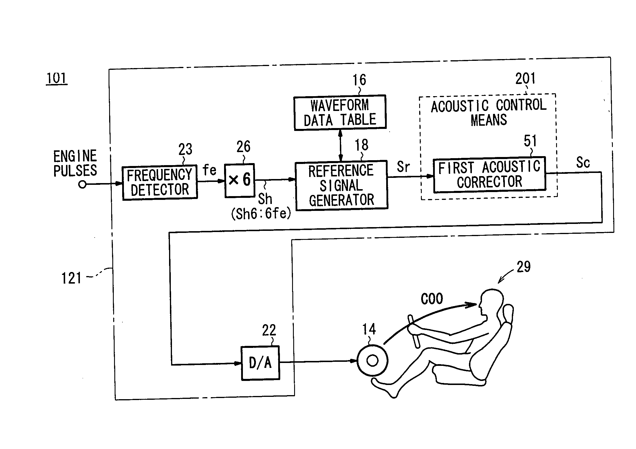
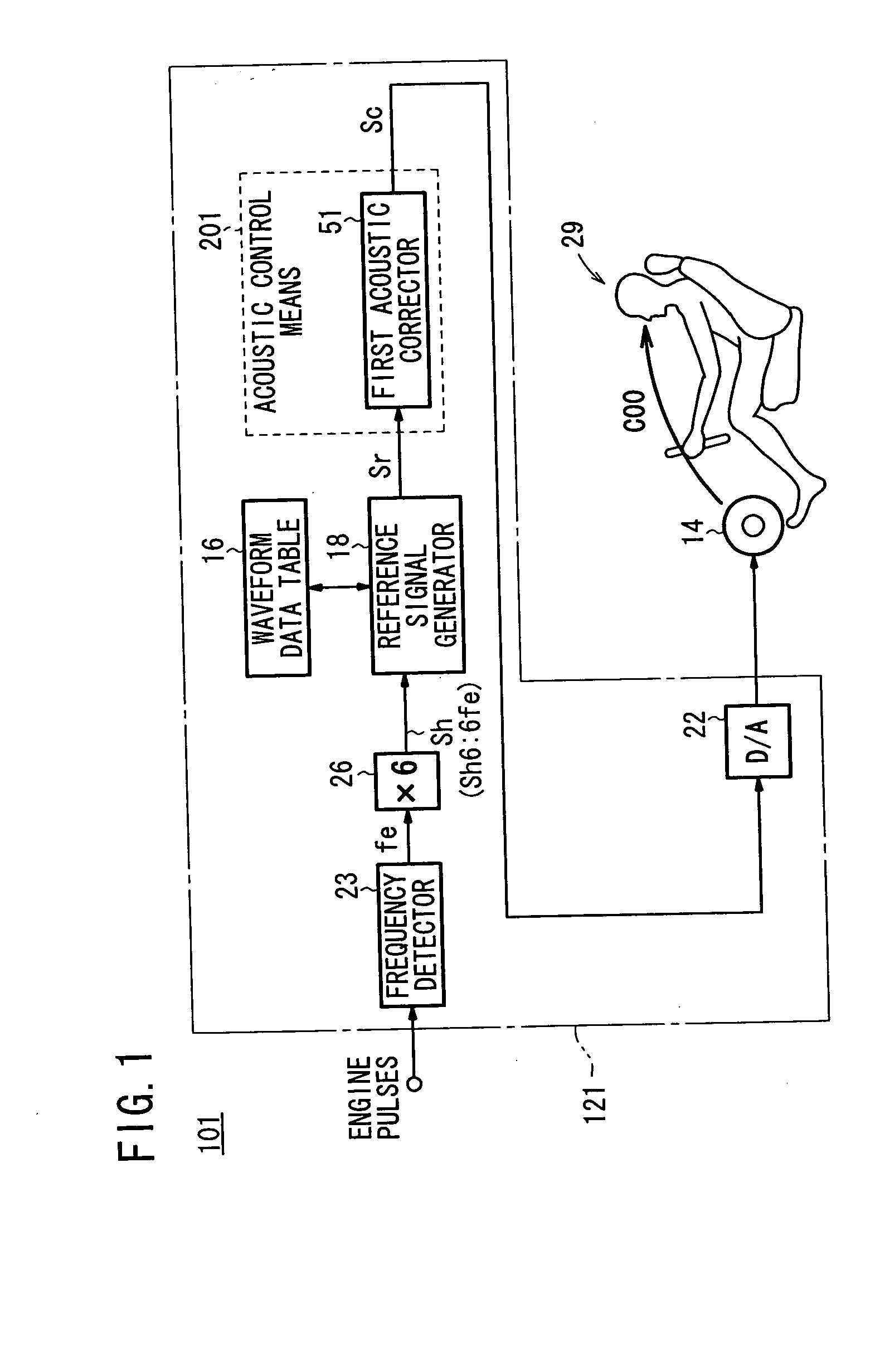
[0056]FIG. 1 shows in block form a mobile object sound effect producing apparatus 101 according to the present invention.

[0057] The mobile object sound effect producing apparatus 101 comprises an ECU (Electronic Control Unit) 121 serving as a general control means, and a speaker 14 serving as an output means.

[0058] The ECU 121 is mounted in the dashboard of a motor vehicle, and essentially includes a waveform data table 16 for storing waveform data in one cyclic period, a reference signal generator 18 serving as a reference signal generating means for generating a reference signal Sr which has a harmonic (harmonic signal) Sh based on an engine rotation frequency fe of the motor vehicle by successively reading waveform data from the waveform data table 16, and an acoustic control means 201 for generating a control signal Sc based on the reference signal Sr.

[0059] The speaker 14 serves to apply sounds to a passenger in a passenger position 29 such as a driver seat or a front passeng...

second embodiment

[0077]FIG. 5 shows in block form a mobile object sound effect producing apparatus 102 according to the present invention. As shown in FIG. 5, the mobile object sound effect producing apparatus 102 comprises an ECU 122 and the speaker 14.

[0078] The mobile object sound effect producing apparatus 102 according to the second embodiment differs from the mobile object sound effect producing apparatus 101 according to the first embodiment in that an acoustic control means 201 comprises the first acoustic corrector 51 and a second acoustic corrector 52.

[0079] The second acoustic corrector 52 comprises a filter or an amplifier functioning as an equalizer for adjusting the amplitude of the reference signal Sr within a certain frequency range.

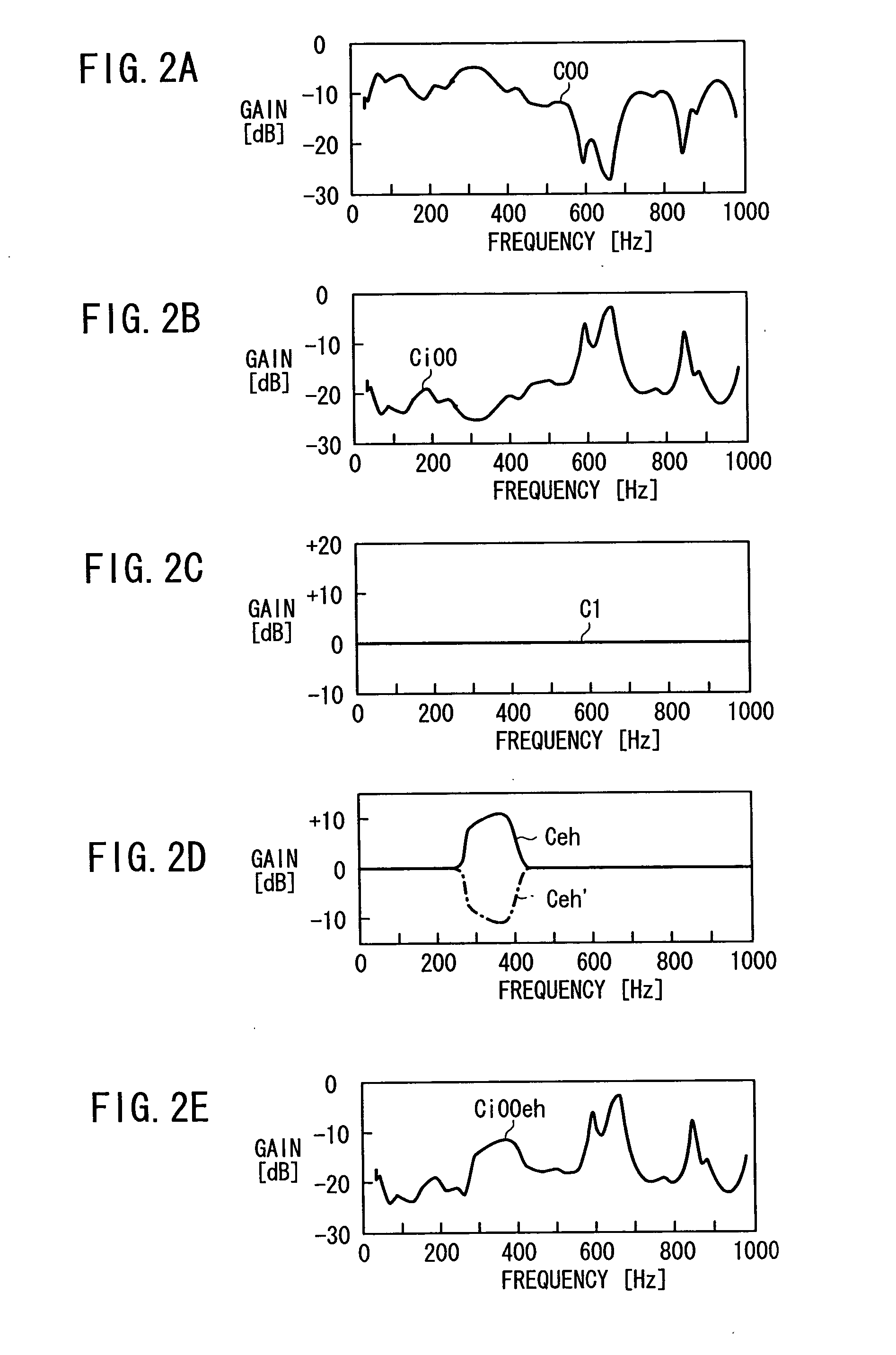
[0080] For example, as indicated by the solid-line curve in FIG. 2D, the second acoustic corrector 52 provides gain characteristics represented by a gain characteristic curve Ceh having increased gains in a frequency range from 300 [Hz] to 450 [Hz], for...

third embodiment

[0083]FIG. 6 shows in block form a mobile object sound effect producing apparatus 103 according to the present invention. As shown in FIG. 6, the mobile object sound effect producing apparatus 103 comprises an ECU 123 and the speaker 14.

[0084] The ECU 123 includes multipliers 24, 25, 26 for converting the engine rotation frequency fe detected by the frequency detector 23 respectively into a frequency 4fe (fourth harmonic frequency), a frequency 5fe (fifth harmonic frequency), and a frequency 6fe (sixth harmonic frequency), which are four, five, and six times, respectively, the engine rotation frequency fe.

[0085] The ECU 123 also includes a reference signal generating means 21 comprising three reference signal generators 18, which are identical to each other.

[0086] The reference signal generators 18 generate respective reference signals Sr1, Sr2, Sr3 based on the engine rotation frequency fe by reading waveform data from the waveform data table 16.

[0087] The ECU 123 further includ...


PUM


Abstract

Gain characteristics depending on the frequency of a reference signal from speakers to a passenger position in a motor vehicle, i.e., gain characteristics which are an inversion of vehicle cabin sound field characteristics, are set in a first acoustic corrector. At the passenger position, a gain characteristic curve that is flat at various frequencies is achieved to prevent gain peaks and dips from occurring at the passenger position. A sound effect generated at the passenger position is made linear depending on the state of a noise source, or more specifically, a noise source caused by an accelerating action on the motor vehicle.

Description

BACKGROUND OF THE INVENTION [0001] 1. Field of the Invention [0002] The present invention relates to an apparatus for producing a sound effect in a mobile object depending on the rotational speed of an engine mounted on the mobile object, and more particularly to a mobile object sound effect producing apparatus which is suitable for use on motor vehicles such as passenger automobiles, aircraft such as helicopters, air planes, etc., or watercrafts such as pleasure boats, etc. [0003] 2. Description of the Related Art [0004] Heretofore, there have been proposed in the art sound effect producing apparatus for detecting an accelerating or decelerating action made by a passenger (driver) on a mobile object, e.g., a motor vehicle, and producing and radiating a sound effect depending on the acceleration or deceleration through a speaker installed in a vehicle cabin into the vehicle cabin, as disclosed in Japanese Laid-Open Patent Publication Nos. 54-8027 and 4-504916 (PCT). [0005] According...

Claims


Application Information

Patent Timeline
IPC IPC(8): H03G3/00H04B1/00
CPCG10K15/02
Inventor KOBAYASHI, YASUNORIINOUE, TOSHIOTAKAHASHI, AKIRASAKAMOTO, KOSUKE
Owner HONDA MOTOR CO LTD
Learn More