Detector detecting transmission performance of optical composite cable

a technology of optical composite cable and detection device, which is applied in the direction of transmission monitoring, instruments, television systems, etc., can solve the problems of increasing transmission loss, disconnection of optical fiber and electric lines, and persisting problems, and achieve the effect of detecting transmission lines, optical composite cables, and quick knowledg

Active Publication Date: 2006-09-28
CANARE ELECTRIC
View PDF3 Cites 4 Cited by
  • Summary
  • Abstract
  • Description
  • Claims
  • Application Information

AI Technical Summary

Benefits of technology

[0014] Effects to be obtained by the present invention are explained as follows.
[0015] The first unit is connected to one end of the optical composite cable. Then other optical composite cables are connected in sequence to the other end of the optical composite cable by cascade connection, and the optical composite cables are extended. The second unit is connected to the other end of the extended optical composite cables, and the detector of the present invention detects the transmission performance of those connected optical composite cables. By carrying out these processes every time the optical composite cable is connected, it becomes possible to quickly know which one of the optical composite cables is broken.
[0016] Also, when the optical composite cables are connected to each other in used state, the first unit is connected to the end of one optical composite cable at the side the TV camera is connected, the second unit is connected to the connector of the optical composite cable which is installed at the farthest side from the first unit, and then transmission performance of the optical composite cable between each end is measured. Next, the optical composite cable is taken off at the farthest side from the first unit, the second unit is connected to the connector of the next optical composite cable in the transmission line which is installed at the farthest side from the first unit, and then transmission performance of that optical composite cable between each end is measured. By carrying out those processes toward the first unit repeatedly, it is detected which one of the optical composite cables has trouble.
[0017] Accordingly, only one of the second unit and the first unit connected to the optical composite cables may be shifted. That enables to detect troubles of transmission line using the optical composite cables extremely easier when the cables are installed in the field.
[0018] As a result, troubles in a transmission circuit comprising optical composite cables which is employed to connect TV cameras to telecast from outdoor can be detected more easily.

Problems solved by technology

In order to install optical composite cables outdoor, however, problems persist in disconnection of optical fibers and electric lines and increasing transmission loss owing to contamination of soiled connection ends of optical fibers and deterioration of the optical fibers and so on.
Accordingly, they need to move a heavy TV camera from one connection end of the optical composite cable to the other, and that bothers to check operation of each optical composite cable to be installed.

Method used


Image

  • Detector detecting transmission performance of optical composite cable
  • Detector detecting transmission performance of optical composite cable
  • Detector detecting transmission performance of optical composite cable

Examples


Embodiment Construction

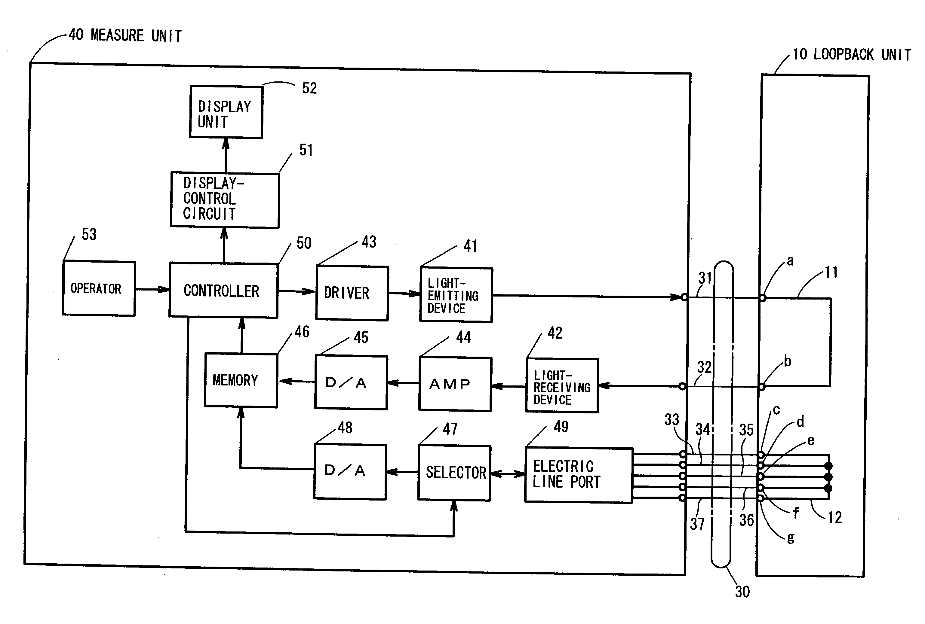
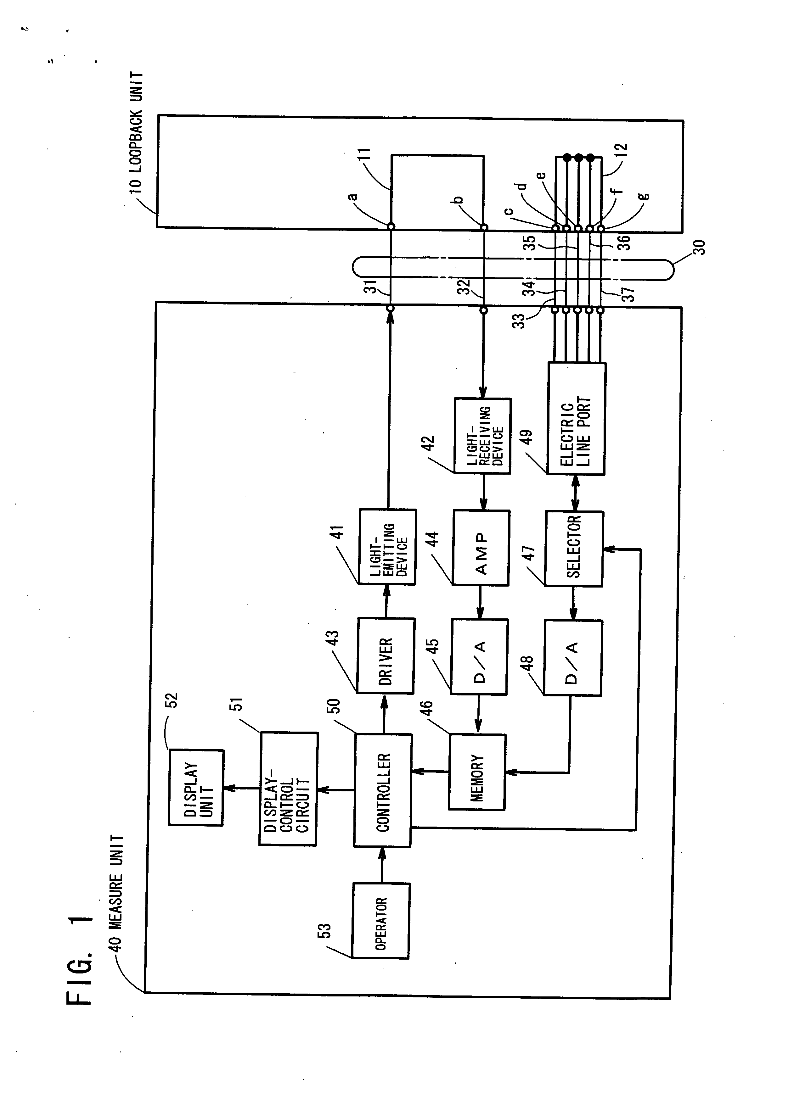
[0023] Embodiments of the present invention will next be described based on concrete examples. The scope of the present invention, however, is not limited to the embodiment described below.

[0024] A detector detecting transmission performance of optical composite cable comprises a loopback unit 10 as a first unit and a measure unit 40 as a second unit. The loopback unit 10 comprises an optical loop part, or a loop fiber 11 which connects an end ‘a’ of a first optical fiber 31 and an end ‘b’ of a second optical fiber 32. The loopback unit 10 comprises a short-circuit part, or a short-circuit wiring 12, which short-circuits the ends c and d of a pair of signal lines 33 and 34, the ends e and f of a pair of signal lines 35 and 36, and the end g of a shield line 37.

[0025] An optical composite cable 30 comprises the first optical fiber 31, the second optical fiber 32, the pair of signal lines 33 and 34, the pair of signal lines 35 and 36, and the shield line 37.

[0026] The measure unit ...


PUM


Abstract

The detector comprises a loopback unit 10 which is connected to a connector formed at one end of an optical camera cable, an optical loop fiber 11 connecting a first optical fiber 31 and a second optical fiber 32, and a short-circuit wiring 12 which short-circuits plural electric lines of the optical camera cable. The detector also comprises a measuring unit 40 comprising a transmission loss measuring part which is connected to a connector formed at the other end of the optical camera cable and measures transmission loss between the first optical fiber and the second optical fiber, a resistivity measuring part which measures resistivity between electric lines, a disconnection detecting part which detects connection or disconnection of electric lines by using measured resistivity, and a display part, which displays the result of transmission loss measured by the transmission loss measuring part and connection or disconnection detected by the disconnection detecting part.

Description

[0001] This is a patent application based on a Japanese patent application No. 2005-86710 which was filed on Mar. 24, 2005, and which is incorporated herein by reference. TECHNICAL FIELD [0002] The present invention relates to a device which detects transmission status of an optical composite cable comprising optical fibers and electric lines. Mainly, the present invention relates to a device detecting disconnection and transmission loss of an optical fiber. BACKGROUND ART [0003] Conventionally, as shown in a patent document 1, i.e., Japanese Patent Application Laid-open No. 2000-59661, an optical composite cable for a TV camera which comprises a pair of optical fibers, a pair of signal lines, and a shield line, is a common and well-known example in order to control a TV camera. Image data and sound signals of a TV camera are transferred through optical fibers, control signals controlling the camera are transferred through signal lines, and electric power is supplied to the TV camer...

Claims


Application Information

Patent Timeline
Patent Type & Authority Applications(United States)
IPC IPC(8): G02B6/44G01R31/02H04B3/46H04B10/07H04N5/225H04N5/232
CPCG01M11/33G02B6/381G02B6/3817G02B6/3827G02B6/3895
Inventor ONISHI, SATORU
Owner CANARE ELECTRIC
Why Eureka
Try Eureka