Digital camera, lens unit, and camera system having the same

Inactive Publication Date: 2006-09-28
FUJIFILM HLDG CORP +1
View PDF3 Cites 74 Cited by
  • Summary
  • Abstract
  • Description
  • Claims
  • Application Information

AI Technical Summary

Benefits of technology

[0011] In view of the foregoing problems, an object of the present invention is to provide a digital camera, lens unit, and camera system having the same, which is suitable in view of reliable transmission of image signals by appropriately constructing contacts for electrical connection in an interchangeable unit for use with a camera body.
[0020] The lens mount portion has a receptacle opening for receiving insertion of the lens unit coupling portion. A first bayonet lug mechanism is disposed on an open end of the receptacle opening, for projecting toward a central axis thereof. The lens unit coupling portion has a second bayonet lug mechanism, disposed to project radially, inserted in a retaining channel defined in a middle of the first bayonet lug mechanism, for rotationally shifting relative to the first bayonet lug mechanism after insertion, to retain the lens unit on the camera body.

Problems solved by technology

However, several attempts are made for saving a mechanical space inside the lens unit because of high density in mounting of relevant parts.
It is extremely difficult to reduce a space in the lens unit in the case of the lens connection contacts and the camera contacts of the above.
No sufficient highness of the communication speed can be obtained in connection with the camera body.
However, it is still impossible to detect an incompletely loaded state.
A problem arises that a user will not be aware of the incomplete of the interchangeable lens.
Image pickup cannot be made.
Also, he or she erroneously determines occurrence of failure because of lack of image signals transmitted to the camera body.
In particular, the problem is serious for a system with the interchangeable lens containing the image pickup device or CCD.

Method used


Image

  • Digital camera, lens unit, and camera system having the same
  • Digital camera, lens unit, and camera system having the same
  • Digital camera, lens unit, and camera system having the same

Examples


Embodiment Construction

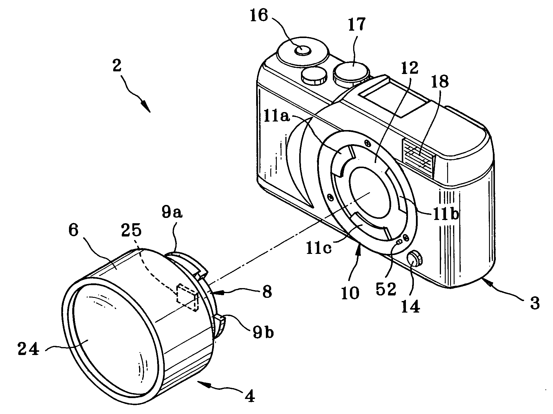
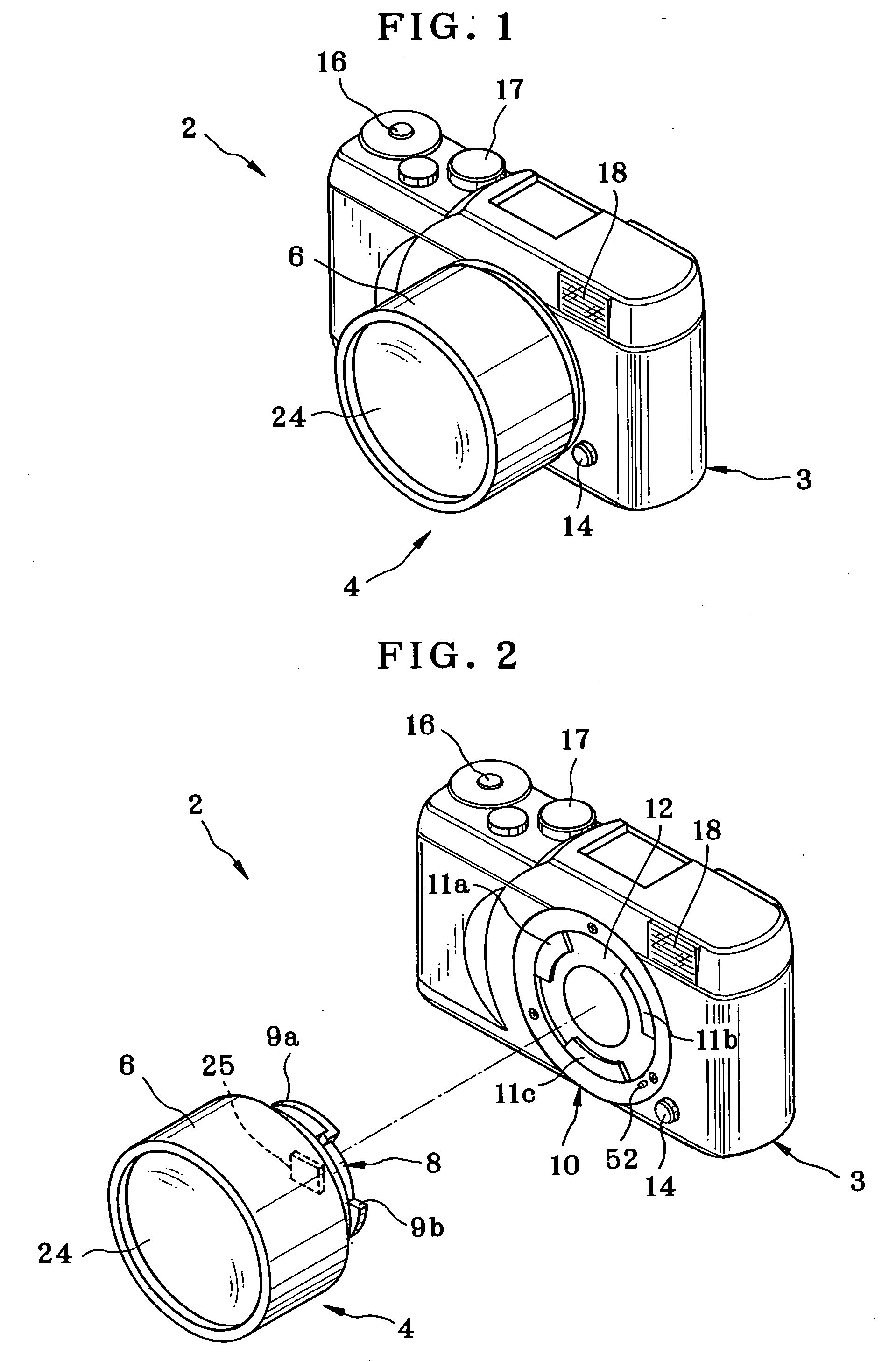
[0067] A digital still camera 2 of the invention is described hereinafter by referring to the drawings. In FIGS. 1 and 2, the digital still camera 2 includes a camera body or camera main unit 3 and a lens unit 4. The lens unit 4 is set on the camera body 3 in a removable manner, and when set suitably, is electrically connected with the camera body 3. In FIG. 1, the camera body 3 and the lens unit 4 in a loaded state on the camera body 3 are depicted. In FIG. 2, the camera body 3 and the lens unit 4 in a removed state are depicted.

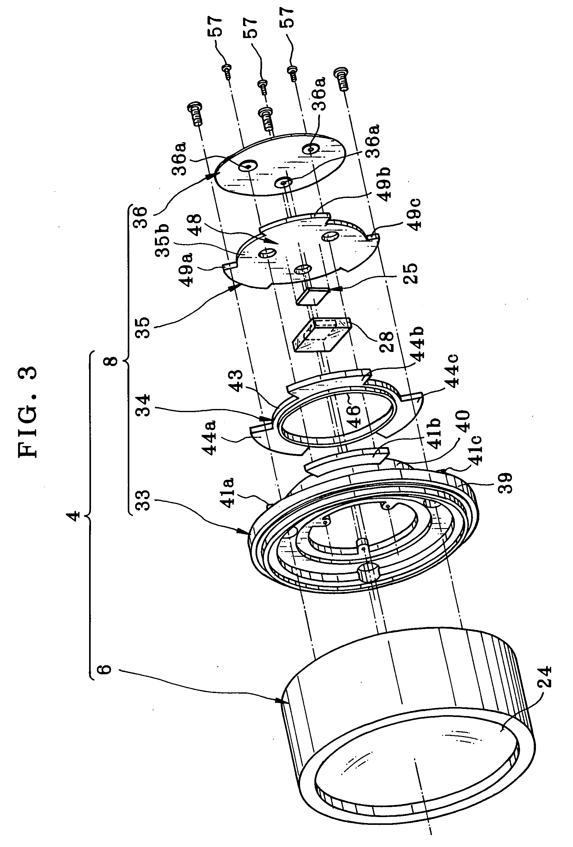
[0068] A lens unit coupling mechanism 8 for mounting is located at the rear end of the lens unit 4. Bayonet lugs 9a, 9b and 9c are included in the lens unit coupling mechanism 8 and protrude as illustrated in FIG. 3. A lens mount mechanism 10 is located on the camera body 3, together with a front panel, a receptacle opening, and a barrel coupling bayonet ring. Bayonet lugs 11a, 11b and 11c are included in the lens mount mechanism 10, and project from the l...


PUM


Abstract

A digital still camera includes a lens unit and a camera body. The lens unit has a photographing lens, and a CCD for image pickup by detecting object light from the photographing lens. The camera body has a lens mount portion adapted to loading of the lens unit, and a camera contact for electrical connection with the lens unit. The lens unit has a lens unit coupling portion, engageable with the lens mount portion, for removable loading on the camera body. A lens connection contact touches the camera contact when the lens mount portion is engaged with the lens unit coupling portion, for electrical connection. A circuit board is connected with the CCD, has a first surface opposed to the camera body. The lens connection contact is mounted on the first surface. In preferred embodiment, a bayonet mechanism couples the lens unit coupling portion with the lens mount portion.

Description

BACKGROUND OF THE INVENTION [0001] 1. Field of the Invention [0002] The present invention relates to a digital camera, lens unit, and camera system having the same. More particularly, the present invention relates to a digital camera, lens unit, and camera system having the same, which is suitable in view of reliable transmission of image signals by appropriately constructing contacts for electrical connection in an interchangeable unit for use with a camera body. [0003] 2. Description Related to the Prior Art [0004] A digital still camera is widely used, and includes an image pickup device or CCD for photographing an image to store the image to a data storage, such as an internal memory, memory card or the like. Various cameras are known, including a unified type in which a camera body includes a photographing lens, and a lens interchangeable type in which the photographing lens is removably mounted on the camera body. [0005] JP-A 2001-116972 discloses a conventional construction o...

Claims


Application Information

Patent Timeline
IPC IPC(8): G03B17/00
CPCG03B17/02G03B17/14G03B19/12H04N5/2254H04N23/55
Inventor TOKIWA, KENTAROTANAKA, HIROSHISENBA, TAKEHIKO
Owner FUJIFILM HLDG CORP
Why Eureka
Try Eureka